
User`s guide

!
!
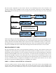
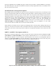
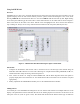
The final system configuration for this exercise will have two C8051F040 processor cards connected to the
common CAN bus of the Car Module as well as several wires and cables connected to the Control Module, and
Meter Module. The block diagram below shows the required electrical connections among the various components
of the exercise.
!
Figure 2: CAN System Layout Diagram.
In the steps leading up to this final configuration, two intermediate configurations will be used. In PART I, the Car
Chassis will be replaced with a NI CAN Demo Box, the Control Module will be replaced with a LabVIEW VI for
sending commands, and the Meter Module will be replaced with another LabVIEW VI, running on a separate PC,
that will be listing the CAN messages and displaying status using various control panel indicators. PART II will
keep the two LabVIEW VIs for the modules while switching the NI CAN Demo Box back to the Car Chassis.
PROGRAMMING TASKS
The first programming task will be a visual programming assignment to develop a more advanced version of the
LabVIEW CAN bus monitoring VI that displays all the status information available from the car. The second, C
programming, task will require the use of the CAN library that has been provided. Documentation for this library
has been provided in HTML format on the course web pages. To interface the 8051 development boards to the car,
plug into the male DB-9 connectors on the cables going to the car base station. The female DB-9 connector is for
use with a debugging device and will not work with the 8051 development boards. For the CAN baud rate to work
correctly, it will be necessary to configure the C8051F040 to use the external crystal oscillator. See can.c where
the CAN rate is specified as 500kbps using the 22.1184MHz crystal oscillator.
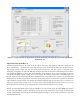
PART I - CAN Basics with LabVIEW & CAN Demo Box
To become familiar with the CAN bus hardware and messages, the first task involves using LabVIEW visual
programs and a National Instruments CAN Demo Box. The programs allow the user to send commands on the
CAN bus and observe them simultaneously using 2 VIs set up on 2 different computers running LabVIEW. Read
CAN/USB interface to PC
running NI LabVIEW tools