
User`s guide

o NI-Tutorial-9759-en.pdf, NI-Tutorial-2862-en.pdf, NI-CAN Channel and Frame API - National
Instruments.pdf, Which NI-CAN Frame API Functions does the NI USB-847x Device Support.pdf
o NI CAN Demo Box and USB-8473s or USB-8473 connector(s)
o Two computers (laptops) running LabVIEW 8.6, 2010 or 2011
o Two Female to Female DB-9 CAN Serial Cables (with terminating resistors - on labeled end)
o Two Female to Female DB-9 CAN Serial Cables (without terminating resistors)
o CAN bus Cable with multiple DB-9 Connectors (Male and Female)
Controller Area Network Interfaces
Overview
The Controller Area Network (CAN) is a serial bus communications protocol developed by Bosch in the early
1980's and is used as a standard for efficient and reliable communication between different nodes in industrial
applications. One prime application upon which this lab is based is the automotive industry where CAN is used to
send data among different nodes in a car.
Each subsystem, such as the engine controller and the instrument panel, shares a common bus for sending and
receiving messages. To make sure that higher priority messages that would directly affect car performance are
given precedence, a CAN data frame contains a message ID, which doubles as a priority code. Frames with a
higher priority (lower ID) win the message arbitration and continue to send the frame whereas those with lower
priority (higher ID) back off and wait to retry until the channel is clear again.
By sending frames with the appropriate ID within the CAN network one can either send a command or send a
request for data. This lab will require setting up two 8051 development boards on a CAN bus. One board will be a
control module that will transmit data only and the other will be a display module that will receive data from the
car. The IDs of different messages are listed in Appendix A.
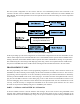
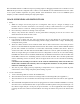
This lab uses a model car that has been set up internally with a CAN controller which receives commands sent to it
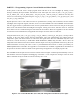
over the CAN bus and activates the various devices in the car, such as the horn, headlights, drive motor, etc. Below
is the block diagram of the internal CAN device. For size, cost, and other factors, it uses a PIC18F25K80
microcontroller rather than a C8051F040 microcontroller. None of this makes any difference to the user since the
tasks for the students only involve sending commands over the CAN bus and the details of the controller receiving
the commands are transparent to the user.
!
Motor%Speed%Control%
Servo%Output%
LED%Output%
Speed%Input%
Temperature%Input%
Current%Sensor%Input%
%
%
%
%
PIC18F25K80%
%System%
Controller%
%
CAN%Transceiver%and%
Interface%
(Airbag%Control%Output)%
Figure 1: Controller Block Diagram for the Car Chassis Module.