
User`s guide
APPENDIX B: Module Pin-outs & Signal Scaling
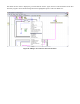
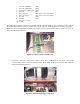
The C8051F040 development boards need to be plugged into the Control and Meter Modules to correctly send and
receive CAN information. Each 10-pin connector should be placed on the pins such that pin 1 of the connector
aligns with pin 1 of the port (except for the DAC, see 2b below. This corresponds to having the end of the
connector with the ribbon on it facing the side that the power to the board comes in on.
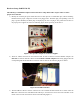
1. The Control Module has three wires and one 10-pin connector.
a. The three separate wires connect to J20:
J20-5 ADC0 input AIN0.0 Green wire from Motor Drive pot
J20-6 ADC0 input AIN0.1 Red wire from Steering pot
J20-8 Analog Ground Black wire
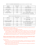
b. The ribbon connector may be attached to any port 1 – 7. You just must keep track of which port is used
when developing the control module software. Pins 1-4 must all be configured as inputs with open-drains
and weak pullups (XBR2.7 = 0). The 10-pin connector reads in values to the C8051F040 as follows:
1. Headlights
2. Right turn signal
3. Left turn signal
4. Buzzer (Horn)
5. Not Used
6. Not Used
7. Not Used
8. Not Used
9. Port Power (+3.3V)
10. Ground
The potentiometers output 0 – 3.3V. With the internal 2.4V reference voltage on the 12-bit channels conversion
values are 0 – 4095 (with the last ~25% of the turn saturating after the voltage rises above 2.4V). The CAN Motor
command accepts a value from 0 – 4095 but the useable range where the motor reacts is ~2300 - ~3075. The can
Steering command value must be in the range from 850 – 2150 and the software must insure the value form the pot
voltage is correctly mapped into this range to prevent damaging the servomotor.
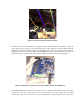
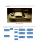
2. The Meter Module has one output wire and two 10-pin connectors. The single wire is for ground and should be
attached to the analog ground screw terminal on the EVB (J20-8). The two 10-pin connectors differ by the
appearance of the red stripes on them.
a. The cable with the solid red stripe is for the port pins and may be attached to any port 0 – 7. You just must
keep track of which port is used when developing the meter module software. Pins 3, 5 & 6 must be
configured as outputs with Push-Pull. The10-pin ribbon cable’s pin-outs from the C8051F040 are wired as
follows:
1. Not Used
2. Not Used
3. Temperature (PWM signal)
4. Not Used
5. Turn left signal indicator (active low)
6. Turn right signal indicator (active low)
7. Not Used
8. Not Used
9. Port Power (+3.3V)
10. Ground
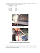
b. The cable with the dashed red stripe is for the DAC outputs. Only the middle two pins are used (J11-3 &
4). These are for DAC0 and DAC1 respectively. Therefore the 10-pin connector should be placed on the 6
pins of the DAC output (J11, see development board manual) such that the 6 pins are centered in the
connector (pins 1 & 2 and 9 & 10 on the cable are unconnected).