
User`s guide
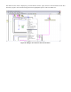
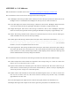

1. Not Used (UART0 TX) (P0.0)
2. Not Used (UART0 RX) (P0.1)
3. Temperature (PWM signal) (P0.2)
4. Not Used (P0.3)
5. Turn left signal (P0.4 & low active logic signal)
6. Turn right signal (P0.5 & low active logic signal)
7. Not Used (P0.6)
8. Not Used (P0.7)
9. Port power (+3.3V)
10. Ground
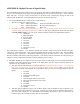
The cable with the dashed red stripe is for the DAC outputs. Only the middle two pins are used (J11-3 & 4). These
are for DAC0 and DAC1 respectively. Therefore the 10-pin connector should be placed on the 6 pins of the DAC
output (J11, see development board manual) such that the 6 pins are centered in the connector (pins 1 & 2 and 9 &
10 on the cable are unconnected).
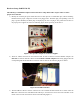
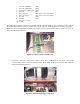
Figure 15: C8051 Connection with R/C Car
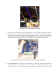
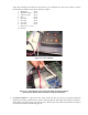
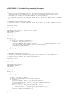
7) If necessary, and with a TA present, check to ensure the 2 - LED lights on the plastic car case are
connected and secured to the CAN Network board. Ideally these should not be removed. The wires are
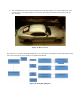
shown in the following Figure 16.
Figure 16: LED Head/Tail Light Connections