
User`s guide
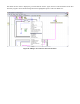
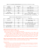
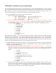

speed. This example uses P3 but users may choose to use a different port. The 10 pin connector (on P3)
reads in values as follows (all are active low logic signals):
1. Headlights (P3.0)
2. Right turn signal (P3.1)
3. Left turn signal (P3.2)
4. Buzzer (P3.3)
5. Not Used (P3.4)
6. Not Used (P3.5)
7. Not Used (P3.6)
8. Not Used (P3.7)
9. Port power (+3.3V)
10. Ground
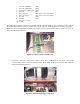
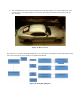
Figure 13: Control Module
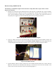
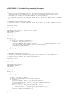
Figure 14: Control Module Connection with C8051 Development Board.
(Note that the ribbon cable is attached to P1 instead of P3 here.)
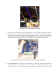
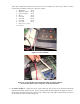
6) The Meter module has 1 output wire and 2 10-pin connectors. The one wire is for ground and should be
attached to the analog ground. The two 10-pin connectors differ by how bright the red stripes on them are.
This example uses P0 but users may choose to use a different port. The cable with the darker red stripe is
for the Port pins and has the following pin-out: