
User`s guide
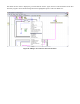
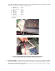
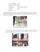
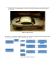
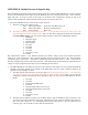
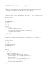

Figure 11: NI USB Connection with CAN MCU
4) The 8051 development boards need to be plugged into the control and meter box modules to ensure the
proper delivery and receiving of CAN information. Each 10-pin connector from the modules should be
plugged in such that Pin #1 aligns with the corresponding Pin #1 on the port of the MCU. If this has been
plugged in correctly, the ribbon should be facing towards the power connection of the board. The red
stripe indicates pin 1 on the left side. This correct configuration is shown in the following Figure 12.
Figure 12: 8051 Power Connection and Control Module ribbon cable Plugged In
5) The Control module has 3 wires and one 10-pin connector. The black wire should be attached to analog
ground (J20-8) and the red and green wires are to be attached to the ADC outputs (J20-6 & J20-5
respectively). These values read in from the two potentiometers are specifically used for steering and