
User`s guide

Hardware Setup (PARTS II & III)
The following is a detailed description of device hardware setup. Please follow steps in order to ensure
proper device function.
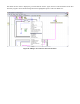
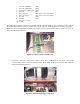
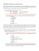
1) Identify the 2 twisted-pair power cables from the car. Each pair has a red and black pair, with the red being
labeled with the proper voltage that it needs to be plugged into. The black plug corresponding to the red
plug is ground. Similarly the black plug accompanying the +5V red plug is also ground. Secure these to
the proper power supplies as seen in the following figure, before powering on the device.
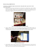
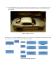
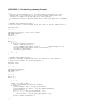
2) There are 3 DB-9 connectors on the CAN bus cable. In order to interface with the NI MCU Adapter, the
male DB-9 Connector must be connected to the Female to Female Adapter before being plugged into the
corresponding blue NI Female DB-9 connection. This is shown in the following Figure 10 below.
Figure 10: NI USB Connection.
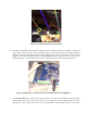
3) The NI USB 8473 Device must be connected to CAN controller mounted inside the car frame. Take the
blue wire connected to the male DB-9 head from Step 2, and connect its end to the CAN controller on the
inside of the car. This connection is shown in the following Figure 11.
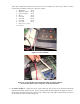
Figure 9: One possible example of +5V Power Supplies.