
User`s guide

Using LabVIEW 2011
Overview
LabVIEW has two main views, the block diagram and the front panel. The front panel can be thought of as the
graphical display where the user interacts directly with the system, and the block diagram as the “code” itself.
Pressing CTRL+E will switch between these two views and CTRL+T will tile them side-by-side. Right-clicking
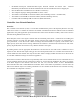
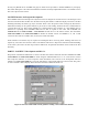
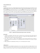
on the front panel will bring up the menu where controls and indicators can be added. This is shown in Figure 7
below. Also shown are the “Run” and “Abort” buttons in the red highlighted area. Never use the abort button to
stop a running VI. Always use the “Stop” button which is included on the front panel (added by the user).
Figure 7: A Blank LabVIEW Panel Showing the Open Control Menu.
Instructions
1. Configure the NI hardware and software tools to send and receive CAN messages. This includes using the
Demo Box and USB connectors to create a bus connecting two computers both running LabVIEW, the RC car,
and the Demo Box. Study the message format and protocol.
2. Now, connect to the RC car. Using the same LabVIEW VIs, edit the block diagrams and/or front panels to
properly display data received from the car. You should also be able to send data to the car and have it respond
appropriately.
3. Finally, implement this LabVIEW functionality in C for the C8051F040 microcontroller.
Adding Sensors
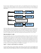
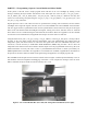
An essential part of the LabVIEW block diagram is the case structure which allows for multiple indicators on the
display to be updated based on the arbitration ID. One of the learning objectives in this lab is to add cases for the
other parts of the car (some are given to start). This means that the ID must be known and the type of indicators