
User Manual

Bluegiga Proprietary Version 1.0
9
6 PIN DESCRIPTION
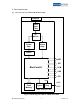
6.1 PIN DESCRIPTION OF WRAP 2022-1-B2B
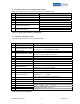
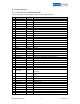
The pin description of WRAP 2022-1-B2B is shown in the table below.
No Pin name I/O Description
1 RESET_IN I Reset if high. (Internal 1 Kohm pull-down resistor.)
2 NC - Not connected.
3 PIO (2) I/O Programmable I/O lines.
4 NC - Not connected.
5 PIO (3) I/O Programmable I/O lines.
6 PIO (4) I/O Programmable I/O lines.
7 PIO (6) I/O Programmable I/O lines.
8 PIO (5) I/O Programmable I/O lines.
9 PIO (7) I/O Programmable I/O lines.
10 NC - Not connected.
11 NC - Not connected.
12 NC - Not connected.
13 NC - Not connected.
14 NC - Not connected.
15 NC - Not connected.
16 NC - Not connected.
17 GND GND Ground.
18 GND GND Ground.
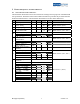
19 PCM_SYNC I/O Synchronous data strobe (pull-down).
20 PCM_CLK I/O Synchronous data clock (pull-down).
21 PCM_IN I Synchronous 8 kbps data in (pull-down).
22 PCM_OUT O Synchronous 8 kbps data out (pull-down).
23 NC - Not connected.
24 NC - Not connected.
25 NC - Not connected.
26 NC - Not connected.
27 SPI_MOSI I Synchronous Serial Interface data input (pull down).
28 SPI_CLK I Synchronous Serial Interface Clock (pull down).
29 SPI_CSB I
Chip select for synchronous serial interface (pull-up).
Active low.
30 SPI_MISO O
Synchronous Serial Interface data output (strong pull-
down).
31 UART_CTS I Asynchronous serial data CTS (pull-up). Active low.
32 USB_D- A USB data minus.
33 UART_RST O Asynchronous serial data RTS (pull-up). Active low.
34 USB_D+ A USB data plus.
35 UART_TX O Asynchronous serial data out.
36 UART_RX I Asynchronous serial data.
37 GND GND Ground.
38 GND GND Ground.
39 5V0 VDD Power supply connection. (Unregulated power input.)
40 3V3 VDD Power supply connection. (Regulated power input.)