
Owner's Manual


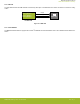
Table Of Contents

4. RF Section
4.1 Introduction
This section gives a short introduction to the RF section of the BRD4207A Radio Board.
4.2 Schematic of the RF Section
The schematic of the RF section of the BRD4207A Radio Board is shown in the following figure.
GNDGND
GND
GND
GND
GND
GNDGND
Ground RF IN/OUT
U1B
ZGM130S
RF_ANT
23
GND
1
GND
10
GND
11
GND
13
GND
12
GND
14
GND
16
GND
17
GND
18
GND
19
GND
20
GND
21
GND
22
GND
32
GND
33
GND
43
GND
48
GND
49
GND
51
GND
53
GND
54
GND
55
GND
64
GND
25
GND
24
P1
SMA
3
2
1
4
5
TP1
C11
R1
0R
NM
R4
0R
NM
R5
0R
NM
L1
R2
0R
ANT1
1
C2
R3
0R
C1
50R_P150R_C2
50R_R4
Antenna
Connector
Printed
Antenna
RF Output
Selection
Low-Pass
Filter
Antenna Tuning
Components
DC
Bypass
Figure 4.1. Schematic of the RF Section of the BRD4207A
The ZGM130S module has an internal balun and matching network, but to ensure safe margins on harmonics in case of transmission
with 14 dBm output power, an external low-pass filter section has been added to the output of the module.
4.3 Bill of Materials for the Low-Pass Filter
The Bill of Materials of the low-pass filter and the DC bypass of the BRD4207A Radio Board is shown in the following table.
Table 4.1. Bill of Materials for the BRD4207A Low-Pass Filter and DC Bypass
Component Name Value Manufacturer Part Number
L1 8.2 nH Murata LQP03TN8N2H02D
C1 3.0 pF Murata GRM0335C1H3R0BA01D
C2 3.0 pF Murata GRM0335C1H3R0BA01D
C11 56 pF Murata GRM0335C1H560JA01D
BRD4207A Reference Manual
RF Section
silabs.com | Building a more connected world. Rev. 1.0 | 8