
Owner's Manual
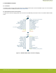
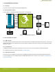
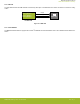
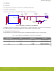
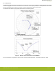
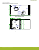
Table Of Contents

3. Radio Board Block Summary
3.1 Introduction
This section introduces the blocks of the BRD4207A Radio Board.
3.2 Radio Board Block Diagram
The block diagram of the BRD4207A Radio Board is shown in the figure below.
EFR32
Printed
Antenna
Radio
Board
Connectors
I2C
24AA0024
Serial EEPROM
RF
Output
Selection
GPIO
UART
Debug
Packet Trace
AEM
I2C
SPI
SubGHz RF
Low
Pass
Filter
SubGHz RF
SMA
Connector
EFR32
ZGM130S
Wireless SiP
GPIO
RGB
LED
SubGHz RF
SubGHz RF
Figure 3.1. BRD4207A Block Diagram
3.3 Radio Board Block Description
3.3.1 SMA Connector
To be able to perform conducted measurements or mount external antenna for radiated measurements, range tests, etc., Silicon Labs
added an SMA connector to the radio board. The connector allows an external 50 Ohm cable or antenna to be connected during design
verification or testing.
3.3.2 Printed Antenna
The BRD4207A Radio Board includes a printed antenna tuned to have close to 50 Ohm impedance at the 863-930 MHz band.
For a detailed description of the antenna, see section
4.4 Printed Antenna.
3.3.3 Radio Board Connectors
Two dual-row, 0.05” pitch polarized connectors make up the BRD4207A Radio Board interface to the Wireless Starter Kit Mainboard.
For more information on the pin mapping between the ZGM130S037HGN2 and the connectors, refer to section
2.2 Radio Board Con-
nector Pin Associations.
BRD4207A Reference Manual
Radio Board Block Summary
silabs.com | Building a more connected world. Rev. 1.0 | 6