
Owner's Manual
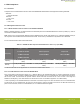
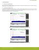
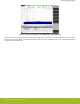
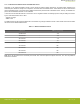
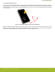
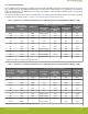
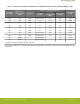

Table Of Contents

7.2.1 Radiated Measurements
For the radiated power measurements, an external whip antenna (P/N: ANT-SS900) was used as a transmitter antenna. It was connec-
ted to the SMA connector of the BRD4207A Radio Board. The supply for the module (VDD) was 3.3 V provided by the mainboard; for
details, see the schematic of the BRD4207A. The transceiver was operated in continuous carrier transmission mode. The output power
of the radio was set to 14 dBm.
The measured radiated powers are shown in the table below. The correction factors are applied based on the Z-Wave Long Range
modulation scheme, showed in section 7.1.2 Conducted Power Measurements with Modulated Carrier.
Table 7.2. Maximums of the Measured Radiated Powers in EIRP [dBm] and the Calculated Modulated Margins in [dB]
Frequency
(868.4 MHz)
Measured Un-
modulated EIRP
[dBm]
Orientation
Z-Wave Long Range Transmission
Limit in EIRP
[dBm]
Correction Fac-
tor [dB]
Calculated
Modulated EIRP
[dBm]
Modulated Mar-
gin [dB]
Fund 11.4 XZ/H NA (0 is used) 11.4 4.7 16.1
2nd -44.0 XZ/H -2.0 -46.0 18.1 -27.9
3rd -61.6 XZ/H -4.5 -66.1 38.2 -27.9
4th -50.4 YZ/V -7.9 -58.3 30.4 -27.9
5th -55.3 YZ/H -9.1 -64.4 36.5 -27.9
6th -54.8 XZ/H -11.5 -66.3 38.4 -27.9
7th -56.3 XZ/H NA (0 is used) -56.3 28.4 -27.9
8th Noise* -/- NA (0 is used) - >20 -27.9
9th -51.1 YZ/H NA (0 is used) -51.1 23.2 -27.9
10th Noise* -/- NA (0 is used) - >20 -27.9
* Signal level is below the Spectrum Analyzer noise floor.
Table 7.3. Maximums of the Measured Radiated Powers in EIRP [dBm] and the Calculated Modulated Margins in [dB]
Frequency
(908.4 MHz)
Measured Un-
modulated EIRP
[dBm]
Orientation
Z-Wave Long Range Transmission
Limit in EIRP
[dBm]
Correction Fac-
tor [dB]
Calculated
Modulated EIRP
[dBm]
Modulated Mar-
gin [dB]
Fund 11.7 XY/H NA (0 is used) 11.7 18.3 30.0
2nd -47.0 XZ/H -2.0 -49.0 >20 -20 dBc
3rd -63.5 XY/H -4.5 -68.0 26.8 -41.2
4th -46.1 YZ/V -7.9 -54.0 12.7 -41.2
5th -48.7 XY/V -9.1 -57.8 16.6 -41.2
6th -49.8 XZ/H -11.5 -61.3 20.1 -41.2
7th -58.4 YZ/V NA (0 is used) -58.4 >20 -20 dBc
8th -53.3 XZ/H NA (0 is used) -53.3 12.1 -41.2
9th -56.2 YZ/H NA (0 is used) -56.2 15.0 -41.2
10th Noise* -/- NA (0 is used) - >20 -41.2
* Signal level is below the Spectrum Analyzer noise floor.
BRD4207A Reference Manual
RF Performance
silabs.com | Building a more connected world. Rev. 1.0 | 16