ZGM130S Z-Wave Long Range Radio Board BRD4207A Reference Manual The BRD4207A Wireless Gecko Radio Board enables developers to develop Silicon Labs Z-Wave® Long Range applications. The board contains a Wireless Gecko Systemin-Package module and it is optimized for operating at 14 dBm output power. With the on-board SMA connector, conducted testing is supported, and it also enables attachment of external whip antenna for radiated tests.
Table of Contents 1. Introduction . . . . . . . . . . . . . . . . . . . . . . . . . . . . . . . . 4 2. Radio Board Connector . . . . . . . . . . . . . . . . . . . . . . . . . . . 5 2.1 Introduction . . . . . . . . . . . . . . . . . . . . . . . . . . . . . . . 5 2.2 Radio Board Connector Pin Associations . . . . . . . . . . . . . . . . . . . . . 5 3. Radio Board Block Summary . . . . . . . . . . . . . . . . . . . . . . . . . 6 3.1 Introduction . . . . .
11. Document Revision History silabs.com | Building a more connected world. . . . . . . . . . . . . . . . . . . . . . . . . 22 Rev. 1.
BRD4207A Reference Manual Introduction 1. Introduction The EFR32 Wireless Gecko Radio Boards provide a development platform (together with the Wireless Starter Kit Mainboard) for the Silicon Labs EFR32 Wireless Gecko System-in-Package modules and serve as reference designs for the matching networks of the RF interfaces.
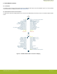
BRD4207A Reference Manual Radio Board Connector 2. Radio Board Connector 2.1 Introduction The board-to-board connector scheme allows access to all ZGM130S GPIO pins as well as the RESETn signal. For more information on the functions of the available pins, see the ZGM130S data sheet. 2.2 Radio Board Connector Pin Associations The figure below shows the mapping between the connector and the ZGM130S pins and their function on the Wireless Starter Kit Mainboard.
BRD4207A Reference Manual Radio Board Block Summary 3. Radio Board Block Summary 3.1 Introduction This section introduces the blocks of the BRD4207A Radio Board. 3.2 Radio Board Block Diagram The block diagram of the BRD4207A Radio Board is shown in the figure below.
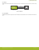
BRD4207A Reference Manual Radio Board Block Summary 3.3.4 RGB LED The radio board features an RGB LED that is controlled by GPIO pins on the ZGM130S. The LED is connected in an active-low configuration. PD10 (GPIO) PD11 (GPIO) PD12 (GPIO) LED_R LED_G LED_B RGB LED ZGM130S Figure 3.2. RGB LED 3.3.5 Serial EEPROM The BRD4207A Radio Board is equipped with a serial I2C EEPROM for board identification and to store additional board-related information. silabs.com | Building a more connected world. Rev. 1.
BRD4207A Reference Manual RF Section 4. RF Section 4.1 Introduction This section gives a short introduction to the RF section of the BRD4207A Radio Board. 4.2 Schematic of the RF Section The schematic of the RF section of the BRD4207A Radio Board is shown in the following figure.
BRD4207A Reference Manual RF Section 4.4 Printed Antenna The BRD4207A Radio Board includes a printed antenna tuned to have close to 50 Ohm impedance at the 863-930 MHz band, while the radio board is plugged into the WSTK. The antenna is not connected to the RF output by default; the RF output selector 0 Ohm resistor should be repositioned from the R2 to the R1 position in order to enable operation with the printed antenna.
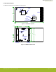
BRD4207A Reference Manual Mechanical Details 5. Mechanical Details The BRD4207A Radio Board is illustrated in the figures below. RGB LED Analog and Digital Supply Filtering Low Pass Filter ZGM130S Module Printed Antenna 30 mm SMA Connector RF Output Selection Antenna Tuning Components 60 mm Figure 5.1. BRD4207A Top View 5 mm 24 mm Board Identification Display Enable Selection 27.3 mm 28.6 mm WSTK Sensor Enable Selection 15 mm Interface Connector Interface Connector Figure 5.2.
BRD4207A Reference Manual EMC Compliance 6. EMC Compliance 6.1 Introduction Compliance of the fundamental and harmonic levels of the BRD4207A Radio Board is tested against the following standards: • 868 MHz: • ETSI EN 300-220-1 908 MHz: • FCC 15.247 921 MHz: • FCC 15.247 6.2 EMC Regulation Emission Limits 6.2.1 ETSI EN 300-200-1 Emission Limits for the 868-868.6 MHz Band Based on ETSI EN 300-220-1, the allowed maximum fundamental power for the 868-868.6 MHz band is 25 mW (14 dBm) e.r.p.
BRD4207A Reference Manual RF Performance 7. RF Performance 7.1 Conducted Power Measurements During measurements, the BRD4207A Radio Board was attached to a Wireless Starter Kit Mainboard which was supplied by USB. The voltage supply for the radio board was 3.3 V. 7.1.1 Conducted Power Measurements The BRD4207A Radio Board was connected directly to a Spectrum Analyzer through its SMA connector. The supply for the module (VDD) was 3.
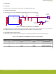
BRD4207A Reference Manual RF Performance Figure 7.3. Typical Output Spectrum of the BRD4207A in the 921 MHz band As shown in the figures, the fundamental is a bit lower than 14 dBm due to the insertion loss of the low pass filter. So, it is under the ETSI and FCC limits in all bands. The unwanted emissions are also under their corresponding limit, so the conducted spectrums are compliant with the regulation limits. silabs.com | Building a more connected world. Rev. 1.
BRD4207A Reference Manual RF Performance 7.1.2 Conducted Power Measurements with Modulated Carrier Depending on the applied modulation scheme, and the spectrum analyzer settings specified by the relevant EMC regulations, the measured power levels are usually lower compared to the results with unmodulated carrier. These differences will be measured and used as relaxation factors on the results of the radiated measurement performed with unmodulated carrier.
BRD4207A Reference Manual RF Performance 7.2 Radiated Power Measurements During measurements, the BRD4207A Radio Board was attached to a Wireless Starter Kit Mainboard which was supplied by USB. The voltage supply for the radio board was 3.3 V. The radiated power was measured in an antenna chamber by rotating the board 360 degrees with horizontal and vertical reference antenna polarizations in the XY, XZ, and YZ cuts. The measurement planes are illustrated in the figure below. X Z Y Figure 7.4.
BRD4207A Reference Manual RF Performance 7.2.1 Radiated Measurements For the radiated power measurements, an external whip antenna (P/N: ANT-SS900) was used as a transmitter antenna. It was connected to the SMA connector of the BRD4207A Radio Board. The supply for the module (VDD) was 3.3 V provided by the mainboard; for details, see the schematic of the BRD4207A. The transceiver was operated in continuous carrier transmission mode. The output power of the radio was set to 14 dBm.
BRD4207A Reference Manual RF Performance Table 7.4. Maximums of the Measured Radiated Powers in EIRP [dBm] and the Calculated Modulated Margins in [dB] Z-Wave Long Range Transmission Frequency (921.4 MHz) Measured Unmodulated EIRP [dBm] Orientation Correction Factor [dB] Calculated Modulated EIRP [dBm] Modulated Margin [dB] Fund 11.0 XY/H NA (0 is used) 11.0 19.0 30.0 2nd -48.3 XZ/H -2.0 -50.3 >20 -20 dBc 3rd -63.7 YZ/V -4.5 -68.2 27.0 -41.2 4th -44.6 YZ/V -7.9 -52.5 11.
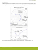
BRD4207A Reference Manual RF Performance 7.2.2 Antenna Pattern Measurements The measured normalized antenna patterns are shown in the following figures. Normalized Radiation Pattern [dB], BRD4207A with WSTK, 868.4 MHz, XY cut 0 315° 270° Normalized Radiation Pattern [dB], BRD4207A with WSTK, 868.4 MHz, XZ cut 0° -5 0 45° -10 315° Normalized Radiation Pattern [dB], BRD4207A with WSTK, 868.
BRD4207A Reference Manual EMC Compliance Recommendations 8. EMC Compliance Recommendations 8.1 Recommendations for 868 MHz ETSI EN 300-220-1 compliance As it was shown in the previous chapter the BRD4207A Wireless Gecko Radio Board is compliant with the emission limits of the ETSI EN 300-220-1 regulation with 14 dBm output power. 8.2 Recommendations for 908 MHz and 921 MHz FCC 15.
BRD4207A Reference Manual Board Revision History 9. Board Revision History The board revision is laser engraved in the Board Info field on the bottom side of the PCB, as outlined in the figure below. The revision printed on the silkscreen is the PCB revision. BRD4207A Rev. A00 123456789 PCB4207A Rev. A00 Board Revision PCB Revision Figure 9.1. Revision Info Table 9.1. BRD4207A Radio Board Revision History Board Revision Description A00 Initial production release. silabs.
BRD4207A Reference Manual Errata 10. Errata There are no known errata at present. silabs.com | Building a more connected world. Rev. 1.
BRD4207A Reference Manual Document Revision History 11. Document Revision History Revision 1.0 Dec, 2020 • Initial document release. silabs.com | Building a more connected world. Rev. 1.
Simplicity Studio One-click access to MCU and wireless tools, documentation, software, source code libraries & more. Available for Windows, Mac and Linux! IoT Portfolio www.silabs.com/IoT SW/HW www.silabs.com/simplicity Quality www.silabs.com/quality Support & Community www.silabs.