UG185: EFR32FG1 2400/169 MHz Dual Band Radio Board User's Guide A Wireless Starter Kit with the BRD4251D Radio Board is an excellent starting point to get familiar with the EFR32™ Flex Gecko Wireless System-on-Chip, and it provides all necessary tools for developing a Silicon Labs wireless application. BRD4251D is a plug-in board for the Wireless Starter Kit Mainboard. It is a complete reference design for the EFR32FG1 Wireless SoC, with matching networks for 19.5 dBm output power, a 2.
Table of Contents 1. Introduction . . . . . . . . . . . . . . . . . . . . . . . . . . . . . . . . 4 1.1 Radio Boards . . . . . . . . . . . . . . . . . . . . . . . . . . . . . . 4 1.2 Ordering Information . . . . . . . . . . . . . . . . . . . . . . . . . . . 4 1.3 Getting Started . . . . . . . . . . . . . . . . . . . . . . . . . . . 4 . . 2. Hardware Overview . . . . . . . . . . . . . . . . . . . . . . . . . . . . . 5 2.
7. Advanced Energy Monitor 7.1 Introduction. . . . . . . . . . . . . . . . . . . . . . . . . . . .25 7.2 Theory of Operation . . . . . . . . . . . . . . . . . . . . . . . . . . . .25 7.3 AEM Accuracy and Performance . . . . . . . . . . . . . . . . . . . . . . .26 7.4 Usage . . . . . . . . . . . . . . . . . . . . . . .26 8. On-Board Debugger . . . . . . . . . . . . . . . . . . . . . . . . . . . . 27 . .
UG185: EFR32FG1 2400/169 MHz Dual Band Radio Board User's Guide Introduction 1. Introduction The EFR32FG1 Flex Gecko Wireless SoC itself is featured on a Radio Board that forms a complete reference design, including the RF section and other components. The Radio Board plugs directly into a Wireless Starter Kit Mainboard. The Mainboard features several tools for easy evaluation and development of wireless applications.
UG185: EFR32FG1 2400/169 MHz Dual Band Radio Board User's Guide Hardware Overview 2. Hardware Overview 2.1 Hardware Layout The layout of the EFR32FG1 2400/169 MHz 19.5 dBm Wireless Starter Kit is shown in the figure below.
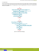
UG185: EFR32FG1 2400/169 MHz Dual Band Radio Board User's Guide Hardware Overview 2.2 Block Diagram An overview of the EFR32FG1 2400/169 MHz 19.5 dBm Wireless Starter Kit is shown in the figure below.
UG185: EFR32FG1 2400/169 MHz Dual Band Radio Board User's Guide Connectors 3. Connectors This chapter gives you an overview of the Wireless STK Mainboard connectivity. The placement of the connectors are shown in the figure below.
UG185: EFR32FG1 2400/169 MHz Dual Band Radio Board User's Guide Connectors 3.3 Breakout Pads Most pins of the EFR32 are routed from the radio board to breakout pads at the top and bottom edges of the Wireless STK Mainboard. A 2.54 mm pitch pin header can be soldered on for easy access to the pins. The figure below shows you how the pins of the EFR32 maps to the pin numbers printed on the breakout pads. To see the available functions on each, refer to the data sheet for EFR32FG1P133F256GM48.
UG185: EFR32FG1 2400/169 MHz Dual Band Radio Board User's Guide Connectors 3.4 EXP Header The EXP header is an angled 20-pin expansion header provided to allow connection of peripherals or plugin boards to the kit. It is located on the right-hand side of the mainboard and it contains a number of I/O pins that can be used with most of the EFR32 Flex Gecko's features. Additionally, the VMCU, 3V3, and 5V power rails are also exported.
UG185: EFR32FG1 2400/169 MHz Dual Band Radio Board User's Guide Connectors 3.4.1 EXP Header Pinout The pin-routing on the EFR32 is very flexible, so most peripherals can be routed to any pin. However, many pins are shared between the EXP header and other functions on the Wireless STK Mainboard. The table below includes an overview of the mainboard features that share pins with the Expansion Header. Table 3.1.
UG185: EFR32FG1 2400/169 MHz Dual Band Radio Board User's Guide Connectors 3.5 Debug Connector The debug connector serves multiple purposes based on the "debug mode" setting which can be configured in Simplicity Studio. When the debug mode is set to "Debug IN", the debug connector can be used to connect an external debugger to the EFR32 on the radio board. When set to "Debug OUT", this connector allows the kit to be used as a debugger towards an external target.
UG185: EFR32FG1 2400/169 MHz Dual Band Radio Board User's Guide Connectors 3.6 Simplicity Connector The Simplicity Connector enables the advanced debugging features, such as the AEM, the virtual COM port and the Packet Trace Interface, to be used towards an external target. The pinout is illustrated in the figure below.
UG185: EFR32FG1 2400/169 MHz Dual Band Radio Board User's Guide Connectors 3.7 Debug Adapter BRD8010A STK/WSTK Debug Adapter is an adapter board which plugs directly into the debug connector and the Simplicity Connector on the mainboard. It combines selected functionality from the two connectors to a smaller footprint 10-pin connector, which is more suitable for space constrained designs.
UG185: EFR32FG1 2400/169 MHz Dual Band Radio Board User's Guide Power Supply and Reset 4. Power Supply and Reset 4.1 Radio Board Power Selection The EFR32 on a Wireless Starter Kit can be powered by one of these sources: • The debug USB cable • A 3 V coin cell battery • A USB regulator on the radio board (for devices with USB support only) BA T U SB AE M The power source for the radio board is selected with the slide switch in the lower left corner of the Wireless STK Mainboard.
UG185: EFR32FG1 2400/169 MHz Dual Band Radio Board User's Guide Power Supply and Reset 4.2 Board Controller Power The board controller is responsible for important features such as the debugger and the AEM, and is powered exclusively through the USB port in the top left corner of the board. This part of the kit resides on a separate power domain, so a different power source can be selected for the target device while retaining debugging functionality.
UG185: EFR32FG1 2400/169 MHz Dual Band Radio Board User's Guide Peripherals 5. Peripherals The starter kit has a set of peripherals that showcase some of the features of the EFR32. Be aware that most EFR32 I/O routed to peripherals are also routed to the breakout pads. This must be taken into consideration when using the breakout pads for your application. 5.1 Push Buttons and LEDs The kit has two user push buttons marked PB0 and PB1.
UG185: EFR32FG1 2400/169 MHz Dual Band Radio Board User's Guide Peripherals 5.2 Memory LCD-TFT Display A 1.28-inch SHARP Memory LCD-TFT is available on the kit to enable interactive applications to be developed. The display has a high resolution of 128 by 128 pixels, and consumes very little power. It is a reflective monochrome display, so each pixel can only be light or dark, and no backlight is needed in normal daylight conditions.
UG185: EFR32FG1 2400/169 MHz Dual Band Radio Board User's Guide Peripherals 5.3 Serial Flash The BRD4251D Radio Board is equipped with an 8 Mbit Macronix MX25R SPI flash that is connected directly to the EFR32. The figure below shows how the serial flash is connected to the EFR32. VMCU VDD PC8 (US1_CLK #11) SCLK PC6 (US1_TX #11) MOSI PC7 (US1_RX #11) MISO PA4 (US1_CS #1) SCS 8 Mbit MX25R8035F EFR32 Figure 5.3.
UG185: EFR32FG1 2400/169 MHz Dual Band Radio Board User's Guide Peripherals 5.4 Si7021 Relative Humidity and Temperature Sensor The Si7021 I2C relative humidity and temperature sensor is a monolithic CMOS IC integrating humidity and temperature sensor elements, an analog-to-digital converter, signal processing, calibration data, and an I2C Interface.
UG185: EFR32FG1 2400/169 MHz Dual Band Radio Board User's Guide Peripherals 5.5 Virtual COM Port An asynchronous serial connection to the board controller is provided for application data transfer between a host PC and the target EFR32. This eliminates the need for an external serial port adapter. Isolation & Level Shift PA0 (US0_TX #0) PA1 (US0_RX #0) PA2 (US0_CTS #30) PA3 (US0_RTS #30) PA5 (GPIO) VCOM_TX VCOM_RX VCOM_CTS Board Controller USB or ETH Host PC VCOM_RTS VCOM_ENABLE EFR32 Figure 5.5.
UG185: EFR32FG1 2400/169 MHz Dual Band Radio Board User's Guide Peripherals 5.5.1 Host Interfaces Data sent to the board controller through the VCOM interface is available in two different ways to the user. At the same time, data can be sent to the target device using these interfaces: • Virtual COM port using a standard USB-CDC driver. • TCP/IP, by connecting to the Wireless STK on TCP/IP port 4901 with a Telnet client. When connecting via USB, the device should automatically show up as a COM port.
UG185: EFR32FG1 2400/169 MHz Dual Band Radio Board User's Guide Peripherals 5.5.3 Hardware Handshake The VCOM peripheral supports basic RTS/CTS flow control. VCOM_CTS (target clear to send) is a signal that is output from the board controller and input to the target device. The board controller de-asserts this pin whenever its input buffer is full and it is unable to accept more data from the target device.
UG185: EFR32FG1 2400/169 MHz Dual Band Radio Board User's Guide Board Controller 6. Board Controller The Wireless STK Mainboard contains a dedicated microcontroller for some of the advanced kit features provided. This microcontroller is referred to as the board controller, and is not programmable by the user. The board controller acts as an interface between the host PC and the target device on the radio board, as well as handling some house-keeping functions on the board.
UG185: EFR32FG1 2400/169 MHz Dual Band Radio Board User's Guide Board Controller 6.1.3 Command Examples PTI Configuration pti config 0 efruart 1600000 Configures PTI to use the "EFRUART" mode at 1.6 Mb/s. Serial Port Configuration serial config vcom handshake enable Enables hardware handshake on the VCOM UART connection. 6.2 Virtual UART The Virtual UART interface provides a high performance application data interface that does not require any additional I/O pins apart from the debug interface.
UG185: EFR32FG1 2400/169 MHz Dual Band Radio Board User's Guide Advanced Energy Monitor 7. Advanced Energy Monitor 7.1 Introduction Any embedded developer seeking to make his embedded code spend as little energy as the underlying architecture supports needs tools to easily and quickly discover inefficiencies in the running application. This is what the Simplicity Energy Profiler is designed to do.
UG185: EFR32FG1 2400/169 MHz Dual Band Radio Board User's Guide Advanced Energy Monitor 7.3 AEM Accuracy and Performance The AEM is capable of measuring currents in the range of 0.1 µA to 95 mA. For currents above 250 µA, the AEM is accurate within 0.1 mA. When measuring currents below 250 µA, the accuracy increases to 1 µA. Even though the absolute accuracy is 1 µA in the sub 250 µA range, the AEM is able to detect changes in the current consumption as small as 100 nA.
UG185: EFR32FG1 2400/169 MHz Dual Band Radio Board User's Guide On-Board Debugger 8. On-Board Debugger The Wireless STK Mainboard contains an integrated debugger, which can be used to download code and debug the EFR32. In addition to programming a target on a plug-in radio board, the debugger can also be used to program and debug external Silicon Labs EFM32, EFM8, EZR32, and EFR32 devices connected through the debug connector.
UG185: EFR32FG1 2400/169 MHz Dual Band Radio Board User's Guide On-Board Debugger 8.2 Debug Modes Programming external devices is done by connecting to a target board through the provided debug connector, and by setting the debug mode to [Out]. The same connector can also be used to connect an external debugger to the EFR32 Wireless SoC on the kit, by setting debug mode to [In]. Selecting the active debug mode is done in Simplicity Studio.
UG185: EFR32FG1 2400/169 MHz Dual Band Radio Board User's Guide On-Board Debugger Note: For "Debug IN" to work, the kit board controller must be powered through the Debug USB connector. 8.3 Debugging During Battery Operation When the EFR32 is powered by battery and the J-Link USB is still connected, the on-board debug functionality is available. If the USB power is disconnected, the Debug IN mode will stop working.
UG185: EFR32FG1 2400/169 MHz Dual Band Radio Board User's Guide Kit Configuration and Upgrades 9. Kit Configuration and Upgrades The kit configuration dialog in Simplicity Studio allows you to change the J-Link adapter debug mode, upgrade its firmware, and change other configuration settings. To download Simplicity Studio, go to http://www.silabs.com/simplicity. In the main window of the Simplicity Studio's Launcher perspective, the debug mode and firmware version of the selected J-Link adapter is shown.
UG185: EFR32FG1 2400/169 MHz Dual Band Radio Board User's Guide Schematics, Assembly Drawings, and BOM 10. Schematics, Assembly Drawings, and BOM Schematics, assembly drawings, and bill of materials (BOM) are available through Simplicity Studio when the kit documentation package has been installed. silabs.com | Building a more connected world. Downloaded from Arrow.com. Rev. 1.
UG185: EFR32FG1 2400/169 MHz Dual Band Radio Board User's Guide Kit Revision History 11. Kit Revision History The kit revision can be found printed on the kit packaging label, as outlined in the figure below. EFR32FG1 2400/169 MHz 19.5 dBm Dual Band Radio Board SLWRB4251D 18-05-16 124802042 A02 Figure 11.1. Kit Label 11.1 SLWSTK6065A Revision history Kit Revision Released Description C00 28 September 2016 Removed coin cell battery from kit due to shipping restrictions.
UG185: EFR32FG1 2400/169 MHz Dual Band Radio Board User's Guide Document Revision History 12. Document Revision History Revision 1.1 March 2018 • Added information about discontinuation of SLWSTK6065A and introduction of SLWRB4251D. Revision 1.0 May 2016 • Initial version. silabs.com | Building a more connected world. Downloaded from Arrow.com. Rev. 1.
Simplicity Studio One-click access to MCU and wireless tools, documentation, software, source code libraries & more. Available for Windows, Mac and Linux! IoT Portfolio www.silabs.com/IoT SW/HW Quality Support and Community www.silabs.com/simplicity www.silabs.com/quality community.silabs.