
Daim Ntawv Qhia Tus Neeg Siv


2. Quick Start Procedure
Required Equipment
•
3 V Power Supply or 3 V Battery
• 2 Digital Multimeters
• 1 ammeter
• 1 voltmeter
• Potentiometer
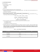
To use the TS1105/06/09 evaluation board, perform the following steps:
1. Configure JP3 so that the Jumper Shunt is connecting VDD to EXT_REF_1, and configure JP2 so that the jumper shunt is con-
necting V
BIAS
to EXT_REF_2.
2. Connect the 3 V power source to RS+ and VDD.
3. Use the voltmeter to measure the V
BIAS
voltage, and adjust P1 potentiometer so that V
BIAS
is 1.5 V.
4. Connect the voltmeter to measure V
OUT
. With no load connected, V
OUT
should be equal to V
BIAS
. The expression for the V
OUT
output voltage is defined by the following equations:
V
O
UT
= V
VBIAS
−
(
GAIN × R
SENSE
×
|
i
SENSE
| )
Equation 1. TS1105 and TS1106 Output Voltage
V
OUT
= V
VBIAS
−
(
GAIN × R
SENSE
× ± i
SENSE
)
Equation 2. TS1109 Output Voltage
5. Connect an ammeter in series from RS– to a potentiometer. Adjust the POT until the ammeter reads:
• TS1105/06/09-20: 500 mA
• TS1105/06/09-200: 50 mA
V
OUT
should equal 1 V, and SIGN should be HIGH.
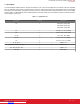
6. TS1106 and TS1109 Only: To evaluate the bidirectional functionality and observe the unipolar or bipolar CSA buffered output
scheme, disconnect the 3 V power supply from RS+ and VDD, as well as the POT connected to RS–. Reconfigure the 3 V power
source by connecting it to RS– and VDD. Connect the ammeter in series from RS+ to the potentiometer. Adjust the POT so that
the ammeter reads the correct ILOAD value for the given part number. The SIGN output will be LOW. Confirm that the output volt-
age matches with the given part number.
Table 2.1. Output Voltages by Part Number
Part Number I
LOAD
V
OUT
TS1106-20 500 mA 1 V
TS1106-200 50 mA
TS1109-20 500 mA 2 V
TS1109-200 50 mA
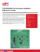
TS1105/06/09 Current Sense Amplifier EVB User's Guide
Quick Start Procedure
silabs.com | Smart. Connected. Energy-friendly. Rev. 1.0 | 2
Downloaded from Arrow.com.Downloaded from Arrow.com.Downloaded from Arrow.com.