
Daim Ntawv Qhia Tus Neeg Siv

Si826x-EVB
4 Rev. 0.1
3. Hardware Overview and Demo
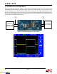
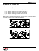
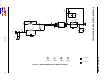
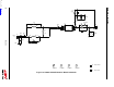
Figure 5 illustrates the connection diagram to demonstrate the Si826x-DIP8 EVB. The other footprint boards
demonstrate in a similar fashion. This demo transmits a 500 kHz (5 V peak, 50 percent duty cycle) square wave
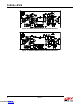
through the ISOdriver to its output (Vo). In this example, VDD is powered by a 15 V supply. Figure 6 shows a scope
shot of CH1 (input) and CH2 (output). Note that if a user wants to evaluate an LED Emulator Input ISOdriver other
than the ones pre-populated, this can be accomplished by removing the installed device and replacing it with the
desired footprint-compatible ISOdriver device.
Figure 5. Summary Diagram and Test Setup
Figure 6. Oscilloscope Display of Input and Output
Output
to Scope
CH2
Signal Input
(500 kHz, 5 Vpk)
Square Wave
Power Supply
(15 V, 100 mA)
Input
to Scope
CH1
+
-
+
-
+
-
Downloaded from Arrow.com.Downloaded from Arrow.com.Downloaded from Arrow.com.Downloaded from Arrow.com.