
Daim Ntawv Qhia Tus Neeg Siv

C8051F50x/51x
Rev. 0.2 5
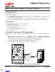
5. Target Board
The C8051F500 Development Kit includes a target board with a C8051F500 (Side A) and C8051F502 (Side B)
device preinstalled for evaluation and preliminary software development. Numerous input/output (I/O) connections
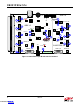
are provided to facilitate prototyping using the target board. Refer to Figure 4 for the locations of the various I/O
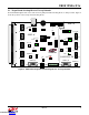
connectors. Figure 5 on page 7 shows the factory default shorting block positions. A summary of the signal names
and headers is provided in Table 12 on page 14.
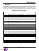
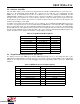
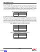
Table 1. Target Board Connector Summary
Connector Description
J1-J5 Side A: Port 0 through Port 4 headers
J7 Header to choose between +5V from Debug Adapter (P2) or +5V from on-board regulator (U6)
J8 Side B: CAN Transceiver (U4) power connector
J9, J10 Side A: External crystal enable connectors
J11 Side B: Connects P1.3_B LED and P1.4_B Switch to MCU port pins
J14 Side A: CAN Transceiver (U3) power connector
J17 Side A: Connects MCU to three separate transceivers (UART(U5), CAN(U3) and LIN(T1))
J18 Side A: Connects VIO to VIO_A_SRC which powers the P1.2 potentiometer, the /RST_A pin
pull-up, and P1.4_A Switch pull-up.
J19 Side A: Connects P1.3_A LED and P1.4_A Switch to MCU port pins
J20 Side A: Connects R27 potentiometer to port pin 1.2
J21 Connect V_HIGH node from TB1 LIN header to +5V regulator input for board power
J22 Side A: Connects decoupling capacitors C28 and C29 for MCU VREF (P0.0)
J24 Side A: Connects +5 V net to VIO and VREGIN of the MCU
J26 Side B: Connects MCU to three separate transceivers (CAN (U4) and LIN (T2))
J27-J29 Side B: Port 0 through Port 2 headers
J31 Side B: Connects +5V net to VIO and VREGIN of the MCU
J32 Side B: Connects decoupling capacitors C41 and C42 for MCU VREF (P0.0)
P1 Side A: 96-pin female connector
P2 Side A: DEBUG connector for Debug Adapter interface
P3 Side B: DEBUG connector for Debug Adapter interface
P4 Power connector (accepts input from 7 to 15 VDC unregulated power adapter)
P5 USB connector (connects to PC for serial communication)
TB1 Shared LIN Connector for Side A and B MCUs for external nodes
TB2 Shared CAN Connector for Side A and B MCUs for external nodes
TB3 Side A: Power supply terminal block
Downloaded from Arrow.com.Downloaded from Arrow.com.Downloaded from Arrow.com.Downloaded from Arrow.com.Downloaded from Arrow.com.