
Daim Ntawv Qhia Tus Neeg Siv


C8051F50x/51x
Rev. 0.2 13
5.12. Potentiometer (J20)
The C8051F500 (Side A) device has the option to connect port pin P1.2 to 10K linear potentiometer. The
potentimeter is connected through the J20 header. The potentiometer can be used for testing the analog-to-digital
(ADC) converter of the MCU.
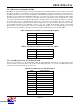
5.13. Power Supply I/O (Side A) (TB3)
All of the C8051F500 target device’s supply pins are connected to the TB3 terminal block. Refer to Table 11 for the
TB3 terminal block connections.
5.14. C2 Pin Sharing
On the C8051F500 (Side A), the debug pin C2CK is shared with the /RST pin. On the C8051F502 (Side B), the
debug pins C2CK and C2D are shared with the pins /RST and P3.0 respectively. The target board includes the
resistors necessary to enable pin sharing which allow the pin–shared pins (/RST and P3.) to be used normally
while simultaneously debugging the device. See Application Note “AN124: Pin Sharing Techniques for the C2
Interface” at www.silabs.com for more information regarding pin sharing.
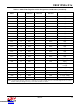
Table 11. TB1 Terminal Block Pin Descriptions
Pin # Description
1VIO_A
2 VREGIN_A
3 VDD_A
4VDDA_A
5GNDA_A
6GND
Downloaded from Arrow.com.Downloaded from Arrow.com.Downloaded from Arrow.com.Downloaded from Arrow.com.Downloaded from Arrow.com.Downloaded from Arrow.com.Downloaded from Arrow.com.Downloaded from Arrow.com.Downloaded from Arrow.com.Downloaded from Arrow.com.Downloaded from Arrow.com.Downloaded from Arrow.com.Downloaded from Arrow.com.