SI-2K Digital Cinema Camera User Manual Thank you for purchasing this Silicon Imaging/P+S Technik Product. Before operating this unit, please read the Instructions carefully to ensure best possible performance. Art.No.
SI 2K Manual
Introduction The SI-2K Digital Cinema Camera and SI-2K Mini Camera Head are camera systems operating in conjunction with SiliconDVR software. SiliconDVR Software controls the SI-2K Mini from either the Recording Unit or a PC Laptop/Workstation. Silicon DVR is preinstalled on the Recording Unit and auto-starts by switching on the Recording Unit. The device is designed to be controlled by a touchscreen monitor. Therefore all dedicated control buttons at the camera have been removed.
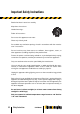
Important Safety Instructions Read all of these instructions carefully. Keep these instructions. Heed all warnings. Follow all instructions. Do not use this apparatus near water. Clean only with dry cloth. Do not block any ventilation openings. Install in accordance with the manufacturer’s instructions. Do not install near any heat sources as radiators, heat registers, stoves, or other apparatus (including amplifiers) that produce heat.
FCC NOTE This device complies with Part 15 of the FCC Rules. To assure continued compliance follow the attached installation instruction and do not make any unauthorized modifications. CAUTION RISK OF ELECTRONIC SHOCK DO NOT OPEN CAUTION TO REDUCE THE RISK OF ELECTRIC SHOCK, DO NOT REMOVE COVER (OR BACK). NO USER SERVICEABLE PARTS INSIDE. REFER SERVICING TO QUALIFIED SERVICE PERSONNEL.
Safety Instructions SI 2K Manual
Contact Information Web Support: http://www.siliconimaging.com/DigitalCinema/ http://www.pstechnik.de/en/digitalfilm-si2k.php Support Forum: http://www.siliconimaging.com/support_forum/index.php In the U.S.A.: Silicon Imaging Inc. 17534 Von Karman Avenue Suite 200 Irvine, CA 92614-6208 USA Phone: 949-650 1766 Sales: hd@siliconimaging.com Support: support@siliconimaging.
Contact Information SI 2K Manual
Table Of Contents Introduction............................................................................................3 IMPORTANT SAFETY INSTRUCTIONS........................................4 Contact Information..............................................................................6 Table Of Contents.................................................................................7 Chapter 1 2 Chapter 3 Chapter 4 Chapter 5 Chapter 6 Apendix A Chapter Delivery Content. ................
Table Of Contents SI 2K Manual
1 Delivery Content Thank you for choosing SI-2K Digital Cinema Camera products.
Delivery Content SI 2K Manual
2 SI-2KSI-2K MINI MINI Mechanical Specifications FRONT 1 62mm 102mm 2 3 72mm BACK 5 4 6 1 IMS Interchangeable Mount System (for Mounts: PL, B4, Nikon, Canon etc.
81mm 81mm 36mm 36mm 1 1 1 25 62mm 26 N 35 N 16 2 105 110 26 3 4 5 7 6 27 8 10 9 11 280,50 20,22 Sensor surface to P+S Technik IMS 19 20 17 13 22 15 23 211,3 12 21 14 15 18 14 24 16 Mechanical Specifications SI 2K Manual
2 SI-2K Recording Unit 1) 2) 3) 4) 5) 6) SI-2K Mini tray with Camera Head connectors and locker bars Hirose 12-pin (+Batt power) Lightweight support prepared for 15 mm rods Handle with vIewfinder holder mechanics Anton Bauer Gold Mount (Battery Mount) HDMI out (Standard Computer DVI Signal Secondary Monitoring 1280x720 60 Hz) 7) Audio I/O left: Sub-D to Breakout Cable, right: headphones out 3.
Mechanical Specifications SI 2K Manual
3 Quick Start Guide SI-2K Mini Camera Head The SI-2K Mini is a small camera head with a 2/3” single chip CMOS sensor working with a Bayer pattern. The frame size is 10.24mm x 5.76mm (w x h) (16mm frame: 10.3mm x 7.5mm) (w x h). The data output of the SI-2K Mini is transfered via Gigabit Ethernet on a Lemo 12 pin connector for maximum reliability. A second connector for I/O and power is also provided. The mounting system for lens mounts relies on the P+S Technik Interchangeable Mount System (IMS).
Mechanical Preparation Mounting the SI-2K Mini camera head The SI-2K Mini is mounted (i.e. to the SI-2K Mini Rig, to the ergonomic hand grip or a tripod) either from the top or bottom by 1/4”x20 mounting holes. Two mounting holes are provided along with one alignment hole. Depending on the mounting system, the mounting holes can be used to provide different spacing between the mounting hole and alignment pin.
Mounting Accessories to the SI-2K Recording Unit 3 The bottom mount on the SI-2K matches a Sony Quick-Lock mounting plate. With a baseplate the Recording Unit can be adapted to various other systems like 16 mm and 35 mm bridge plates available from Silicon Imaging and P+S Technik. Rosettes are available at both side, the front and back of the camera for accessory mounting. The front of the SI-2K is prepared for lightweight lens support and accepts 15 mm rods.
Inputs & Outputs Power SI-2K Mini Camera Head For standalone operation, power is applied to the PWR/CTRL, either from a battery pack such as the Anton Bauer Dionic 90 via the Mini Rig battery holder or from an AC power supply using the appropriate cable. The data is transmitted over a separate cable from the NETWORK connector to a workstation or laptop computer. For operation tethered to an SI-2K Recording Unit, a special tether cable is used with integrated power and data over the single NETWORK connector.
output capable of display of 720p live video at full resolution. The SI-2K Mini only requires power and data connections since the remainder of the functions are provided by the computer attached to the SI-2K Mini. 3 Power Switch Please use the power switch on the right side of the camera to power down the camera prior to removal of the battery pack. Expect a delay of up to 30 seconds from the time power is applied to the live operation of the camera.
viewfinder. Secondary Monitoring: The HDMI signal is used to show the secondary display which is a representation of the image recorded, it shows up without user interface and can be turned on and off inside SiliconDVR user interface. The HDMI Port at the SI-2K Recording Unit carries a DVI Signal (1280 x 720 @ 60Hz). By using off-theshelf HDMI to DVI Converters every kind of DVI Monitor can be fed.
3 Recording Data and Storage SI-2K Mini Camera Head In addition to supplying power, the PWR/CTRL connection can be used for an external RECORD switch input and for hardware synchronization of multiple cameras using special cables provided by the manufacturer. The NETWORK input is a standard Gigabit Ethernet data path using a more rugged Lemo connector for better data integrity.
In addition, any mapped hard disk can be used for recording. This includes any device that are connected via the external USB ports. Be sure that any external drive supports a sustained throughput of 40 MB/sec. Two extra USB 2.0 ports are available on the back. IMPORTANT: If you want to use additional USB recording devices on the SI-2K please always add and remove them on and from the RUNNING SYSTEM (hot plug).
3 Start the Camera • • • • Connect Accessories like Viewfinder or VGA or DVI Monitor. Connect Powersupply or Battery Dock your Magazine and Turn it on with the knob at the docking frame. Switch on the SI-2K Recording Unit Boot time takes about one minute. Camera Operation To operate the camera either use the LCD Touchscreen functionality or in addition use the integrated mouse pad on the left side of the camera body.
IMPORTANT: Please note, that the software is designed for cross system use. That means that functionality could exceed recording systems which are restricted in performance. That makes the system futureproof in terms of upgrade options, but the user has to be careful in choosing settings. Inside SiliconDVR go to UTILITY MENU/CAM PREFS to access Recording and View Settings. Notes on CAM PREFS Settings: Overall Performance and Stability of the System are depending on the Settings you choose inside CAM PREFS.
this can pose a big problem. Fan mode 2 will keep the fans quiet no matter what, although again, recording will stop at 100C. But once recording stops, the fans kick in at full-speed to keep the camera as cool as possible before the next recording. 3 Set Resolution and Frame Rate • Browse to RESOLUTION / FRAME RATE and choose i.e.: 2048 x 1080 @ 25p • Confirm RESOLUTION / FRAME RATE with OK • After that, the System will prompt to “SET BLACK”. Close Lens and Iris to Set Black with for all Gains.
The frequency of having to SET BLACK will depend on the shooting environment and the subject matter. Typically after approximately five minutes from a cold boot, the camera will reach a temperature stabilization point where any further deviation will be insignificant compared to that which occured in the first five minutes.
3 Note: The on-screen Hotspots inside the picture area are touch sensitive for quick access tools for focus and exposure control. The picture below shows the arrangement of the hot spots. For a detailed explanation of tools and the menu structure of SiliconDVR in general refer the the chapter SiliconDVR > User Interface False Color Exposure Meter: Luminance Distribution in a Scene on a pixel per pixel basis. Red is clipped and therefore overexposed. “Colour Temperature” shows the Luminance.
Look Control The idea behind Iridas Looks is to SIMULATE the color characteristics of the target medium such as a Filmprint or even an HD Monitor, since the RAW image itself looks flat. Please note that this is only a tool to simulate colors inside the SiliconDVR without affecting the RAW Image itself! Iridas .look files represent non-destructive color metadata based on 3D look up tables in a 32-bit floating point environment.
4 SiliconDVR Software Software Activation and Licensing There are two levels of software activation required for a fully operational workflow: 1) the CineForm RAW encoder that works in conjunction with the SI-2K DVR application to encode the video stream, and the CineForm editing tools for your editing suite. Silicon DVR is the Control Center for Recording and Camera Setup. A requirement to run Silicon DVR on the Camera or on a separate Workstation is the License and the Activation.
How to de-activate or re-activate SiliconDVR Note: Please note, that you only have limited number of activations, you can activate your SiliconDVR three times. For re-use please take care to properly deactivate your system. We strongly recomend to contact our technical support team before de-activating or re-activating your license. Please email to helpdesk@pstechnik.de What shall I do if SiliconDVR is not activated You need a separate internet connection line.
4 Notes on Write Protection Filter Quit SiliconDVR (UTILITY MENU – QUIT), the Windows Desktop shows up. A folder named "SI" on the desktop links to all necessary Windows Functions such as Windows Shutdown or ActivateRaw.exe. The “Write Filter” toolset to turn on and off the Write Filter is situated here.
- After these activities are completed in disabled mode, there is another shortcut, “Enable Write Filter and Reboot”. Selecting that will re-enable the Write Filter and reboot. After the reboot, the Write Filter will be enabled and the system will be ready for normal use. The state of the Write Filter (enabled or disabled) can always be determined by opening a console window and typing “fbwfmgr”.
4 Prospect 4K Note: Any editing suite used in conjunction with a CineForm tool should be installed prior to the CineForm application. Once installed, run the Activate.exe utility located in the Windows Start Menu: Start > All Programs > CineForm > Prospect4K Copy the 8-digit System Code from the dialog box. Then, go to the registration site: http://www.cineform.com/register.html and enter the system code, serial number company name, and email address.
SiliconDVR User Interface SiliconDVR consists of three main user interface screens to make general settings, operate the camera and playback recorded clips. In the following the three menu screens UTILITY MENU, MAIN MENU and PLAYBACK MENU and their tools are described in order of first use. The Status Information is visibly in all three menu screens. Status Information Status indicators are placed at the top of the screen to indicate the current settings and mode of the camera.
4 Utility Menu Always leave the MAIN MENU and go to the UTILITY MENU, when you first start the camera to make the basic settings and create a project name. Access the UTILITY MENU from the upper right corner of the MAIN MENU. Each time the Record mode is entered, a new file will be created in the Project directory with a file name of the project followed by a timestamp. This creates an easy sequence of takes automatically.
Quality 4) 3.5:1, or approximately 18-20MB/s from a 2K/24P stream at 0db gain. Quality 3) 5:1 compression, or approximately 15-16MB/s from a 2K/24P stream at 0db gain. Quality 2) 8:1 compression (approx), or approximately 10MB/s from a 2K/24P stream at 0db gain. Quality 1) 10:1 compression, or approximately 8MB/s from a 2K/24P stream at 0db gain. • 12 Bit Uncompressed Uncompressed raw sensor data (as opposed to Cineform RAW™ ) is streamed to the hard disk.
4 Project Setup The Open Project and New Project buttons allow the user to create a new project or open a previously existing project. • New Project The project setup screen selects the location for the main project file (.sil) and all of the individual captures. The project can be stored on any drive - exepect the system drice C:\ - with a drive letter mapped into the system representing an internal, external or network share as long as the continuous throughput to the drive is at least 15MB/sec.
Color Bars A standard color bar pattern can be sent to the display monitors – both the internal and an external. This pattern assists the user in doing a color alignment. A properly aligned monitor is strongly suggested in conjunction with 3D LUT ‘looks’ to view the actual look as it will appear. Flip Image Ground glass converters require that the incoming video image be flipped, top to bottom or left to right for correct viewing.
4 Main Operation Menu Black Setting During the initial use, the software will detect a lack of a black reference image and automatically requests the capture of a reference: Completely cover the lens and click on OK. This performs two functions. First, the image black level is set for every pixel. Second, a bad pixel map will be created for any pixels that are outside of the normal range of offsets and corrected automatically in the RAW file. There are two control areas of the viewfinder.
Resolution/Frame Rate The standard resolutions supported are 2K (2048x1152 / 2048x1080 / 2048x856 ), 1080p (1920x1080), 720p (1280x720), 540p (960x540). For 2K, the supported frame rates are 23.976 and 24fps. For 1080p, the supported frames rates are the same as 2K plus 29.97 and 30fps. For 720p, the frame rate is currently 72fps. An upcoming software release will add 12, 18, 21, 23.976, 24, 25, 30, 48, 50, 60, 72 to the already existing 85 fps. In time-lapse mode, every N th frame is captured.
4 RAM Buffer Indicator The buffer space allocated in the CAM PREFS menu is used to buffer the incoming video. This buffer space is shown visually and numerically. When the buffer is filled, the recording operation will stop. No data to that point will be lost but no further data can be recorded until the buffer is emptied to disk. The buffer gauge is an excellent troubleshooting tool. A slowly rising buffer indicates that the CPU is not able to compress the incoming data at a fast enough rate.
Edge-Based Focus Assist When the focus assist is enabled, a real-time Sobel edge detector is run. As an edge in the picture turns redder, it is in better focus. This is because the edge is sharper. This does not mean that the smoother areas are out of focus, just that they have no well defined edges. Record A recording can be begun either by using the touch button Record at the lower left or by using the hot spot in the lower left.
4 Histogram A real-time histogram is displayed across the bottom of the image. Individual channels of red, blue and green are shown. This is a total histogram of the image showing the number of pixels (vertical axis) vs. the digital value from dark to bright on the horizontal axis. Full Screen Full screen sequences through three states.
Additional Tools Spot Meter/Loupe A 10 pixel by 10 pixel section of the display is enlarged with a 4x zoom. This spot meter shows the average luminosity within the enlarged area. If a white balance is done while the spot meter is active, only the white region within the loupe is used for the white balance. Frame Store Operations There is a single frame buffer that can be used for previewing of compositing effects and single frame capture.
5 Look Control Set Look and Look Library The SET LOOK command opens the LOAD CAMERA LOOK LIBRARY. Inside this library control panel are a selection of up to 4 .looks that can be loaded and quickly selected between, and also controls for modifying those looks, selecting preview and record LUT‘s, and managing which .look files are placed inside of a project‘s folder for inclusion with recorded files.
There are two important columns of note in the LOOK LIBRARY, the REC and VIEW selection columns. When the ENABLE SEPARATE PREVIEW LUT check-box is selected, this allows the end-user to select a different .look file for recording and embedding as metadata in the header of the AVI/QT file, versus what will be viewed on screen.
5 IRIDAS Color Correction Mode Hitting the MODIFY button in the LOOK LIBRARY will open up the IRIDAS color-correction control panel. This control panel has a powerful set of comprehensive controls that allows the end-user to color-correct the preview image in real-time to obtain the look for the image they desire in-camera. It utilizes the same 32-bit floating point color-correction engine of the IRIDAS SpeedGrade OnSet family for high-precision color-correction operations.
Right-clicking on any of the color-adjustment widgets activates a „virtual trackball“ mode. This allows the user to move the mouse around like a trackball control for fine increments of the image. This is especially effective with the color-hue wheels in CONTROL SET 1. To exit the virtual trackball mode, rightclick a second time. Clicking on the histogram indicator swaps between a live histogram and a vectorscope.
5 Keyer Module The Keyer mode in the IRIDAS color correction panel is a special mode that allows users to preview keys on-set in the context of the subject they are shooting. Keys can be set on either green or blue-screen using a real-time RGB difference keyer, and backgrounds can be composited behinds subjects to give the shooter an indication of how a final key and composite in post will look.
The RGB difference keyer works on a „threshold“ principal, where the lower the threshold, the more green or blue is keyed out. The general workflow is that the user picks the screen color using the GREEN or BLUE buttons, and then reduces the threshold until a proper key is made.
6 Shooting with the SI-2K Lens Selection The lenses used with the Silicon Imaging cameras will have tremendous effect on the final quality of the image. No amount of post processing can repair content shot with poor optics. C-Mount The requirements for a C-mount lens to work: 1) The lens must be C-mount and not CS-mount (same thread, different back focal length, the CS-mount is used mostly for surveillance) 2) The lens must have an image circle of at least 2/3" (the real sensor size is 10.24 mm x 5.
Cleaning Optics Ideally, the optics behind the optical low pass filter (OLPF) should remain clean. If debris does get behind the filter, two screws with pads to protect the filter can be removed to give the user access to both the back of the filter and the sensor cover glass. All cleaning should be done with the same care as would be shown with a quality lens. First, compressed air should be used (without shaking the can to avoid spraying propellant).
Exposure Control 6 Introduction And RAW Pipeline CMOS Sensor RAW 12-bit Linear Black Calibration 10-bit LOG Curve CineForm Raw Codec Layer 3: Filters & Effects Layer 2: “Look” Metadata Layer 1: RAW 10-bit log Figure 5.1: RAW Data Pathway At the heart of the SI-2K camera system is an AltaSens 2/3" CMOS sensor with an overall dynamic range of 69 db from the noise floor to white-clip.
The layer-based approach of the CineForm RAW™ codec allows a host program that does not have the ability to natively work with RAW data, such as all current NLE systems and post-compositing tools, to work with the RAW file formats as if it was another native RGB/YUV codec file by “wrapping” the RAW data in an AVI or QuickTime format and then presenting that data to the program in a native format it can read.
Note: The exposure controls monitor the RAW 10-bit log data, not the modifications of a .look file 3D LUT. This is so the D.P. can see the effects of exposure on his digital negative, providing as much information as necessary to get the look desired rather that accidentally clipping data because the .look 3D LUT was higher-contrast and masking valuable information to maintain a proper exposure at the RAW data level.
By exposing “to the right”, the D.P. sets the camera’s exposure so that for a given scene, as much of the scene value information as possible is contained towards the right-side of the histogram without letting values clip. Using this methodology in combination with the 6-zone exposure meter, the D.P.
A Technical Specifications Digital Cinema Initiatives Compliant 2K Digital Cinema Camera • 2/3" 16:9 high-dynamic range CMOS Imaging sensor with 5um pitch • Full-raster, 2K DCI-compliant resolution progressive scan sensor • Direct-to-Disk Recording • AVI and Quicktime files compatible with widely spread Cineform De coders and Iridas Products • Removable Optical Low Pass Filter • 12 bit A/D conversion and 48 bit digital signal processing • 10+ F-stops dynamic range • 180° film shutter equivalent with variab
• Cineform 3.
A • 2-4x Digital Focus Assist • 4x Loupe and integrated spot meter and focus tool • Safe-zone Markers for 16:9 / 4:3 / 1.85:1 / 2.35:1 • Virtual VTR interface • File management and metadata capabilities Audio and SMPTE Timecode Support • L/R balanced line-level inputs with 16-bit/48Khz sampling • L/R balanced line-level outputs with 16-bit/48Khz sampling • Audio Recording multiplexed into .
Technical Specifications SI 2K Manual
Dealer and Partner Contacts In the U.S.A.: Silicon Imaging Inc. 17534 Von Karman Avenue Suite 200 Irvine, CA 92614-6208 USA Phone: 949-650 1766 Sales: hd@siliconimaging.com Support: support@siliconimaging.com In Europe: P+S TECHNIK GmbH Siemensstraße 12 D-85521 Ottobrunn / München GERMANY Tel +49 (0)89 45 09 82 30 Fax +49 (0)89 45 09 82 40 Email: info@pstechnik.de Web: www.pstechnik.