
Silfab Installation Manual
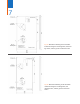
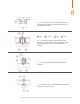
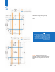

Fig. 4b: modules attached to supporting structure
(rail, item 01) using a clamp (item 02) fixed with a bolt
(item 03) and nut (item 04) – view between two
modules.
1 Rail 2 Clamp 3 Bolt 4 Nut
Fig. 4d: end of module row with additional spacer (item
05: 50mm x 30mm x 24mm)
Fig. 4c: modules attached to supporting structure –
side view
8
Fig. 4a: cross section of a mounting clamp to be used
for attaching the modules to support structure (mini-
mum length is 40 mm).
Document Number: MAN-SFO-06 | SAFETY AND INSTALLATION MANUAL FOR PHOTOVOLTAIC MODULES