
Silfab Installation Manual

6
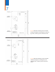
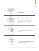
8.2 Module Mounting Method using mounting holes
Each module must be securely fastened at a
minimum of 4 points.
Only use the 4 pre-drilled mounting holes (slots, see
Fig. 3a/3b) on the PV module frame to bolt the
module with M6 (1/4”) stainless steel screws and
nuts to the mounting framework.
The distance of the mounting holes has been
designed in order to result in a uniform wind and
snow load without damaging the module.
Do not drill additional holes in the module
frame; doing so will void the Warranty.
8.3 Mounting using clamping method
Silfab recommends the use of clamps with a design
as shown in Fig. 4a (or equivalent). The use of
improper clamps will void the Warranty.
• These modules can be installed in either Portrait
(vertical) or Landscape (horizontal) configuration.
Refer to Fig. 4 b, c, and d for an example of attach-
ing the modules to a support structure using mount-
ing clamps. Use stainless steel hardware.
• These modules can be mounted on continuous
base structures (inclined or horizontal) such as rails
or similar.
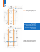
• Both base structures must be mounted at the
same distance from the symmetrical axis (portrait
or landscape) of the module (Fig. 5a/5b).
• Placing the supporting elements as per Fig. 5a/5b
is necessary in order to maintain a correct load
distribution and achieve the minimum UL1703
design load rating of 30 lb/ft2 and IEC61215
2400 Pa load rating.
• When clamping the modules on a support struc-
ture, the following rules have to be applied in order
to maintain the resistance against static loads as
certified:
If the bars or rails run parallel to the module’s
horizontal frames, they have to be placed nearby
the mounting holes (±50 mm (±2’) of the mounting
hole) in order to achieve IEC61215 5400 Pa (113
lb/ft2) downward applied load rating. Please see the
blue mounting zone sections in Fig. 5a/5b.
If the bars or rails run parallel to the module’s
vertical frame, they have to be placed within the
spacing of 500-750 mm (19 11/16 – 29 1/2”) in
order to achieve the UL1703 design load rating of
30 lb/ft2 and IEC61215 2400 Pa load rating. Please
see the orange mounting zone sections in Fig.
5a/5b.
The modules can also be secured by placing the
framed module on a structure that is supporting the
two vertical sides of the frame covering the entire
length. In this case, the position of the mounting
clamps must be in accordance with the above
mentioned spacing(s) – refer also to Fig. 5a/5b.
Please see the orange mounting zone sections in
Fig. 5a/5b.
Document Number: MAN-SFO-06 | SAFETY AND INSTALLATION MANUAL FOR PHOTOVOLTAIC MODULES