
Silfab Installation Manual


Mechanical Installation
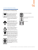
• Do not scratch or break the corrosion-resistant
coating (e.g. anodization layer) on PV Modules and
mounting system.
• Use corrosion-resistant material (e.g. stainless steel
SUS 316) for components (e.g. nuts, bolts, gaskets,
etc.) to install your PV system.
• For safe mounting system installation, use insulation
gaskets between mounting and grounding hardware
attached to the PV module frame and between PV
module frame and rail.
• For safe clamping installation method, use insulation
gaskets between clamp and PV module frame, and PV
module frame and rail.
• Recommendation for gasket insulation are mica
lamination, or silicone, or fluoride made insulating
material.
Grounding
• Silfab recommends to protect the grounding points of
the PV system with an insulating pad, for example (a)
Butyl Plaster to completely cover grounding block or (b)
spray fluorocarbon varnish of 40 um thick onto ground
blocks thoroughly to form an anti-corrosion coating.
Remember to clean the grounding block and surround-
ing area and make sure the surface is dry. The compo-
nents must be fully covered from exposure to salt.
To ensure optimum module performance, Silfab recom-
mends maintenance service every three months with
the following measures:
• Check the module frame, mounting system, grounding
block and junction areas for potential signs of corrosion.
• Clean the module frame, mounting system, grounding
block and junction areas from accumulation of dust
and/or salt with soft foam materials, non-woven fabrics,
whisks, soft sponges, soft brushes and hair brushes
may be used.
• Upon possible finding of corrosion due to salt, re-apply
Butyl Plaster or fluorocarbon varnish to cover rusty area
thoroughly.
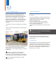
9.4 Silfab Smart Modules
This section of the installation manual is specific to
Silfab Smart Modules (SSA and SSG), which use
Tigo Energy's integrated junction box.
For residential, commercial and utility scale photo-
voltaic solar arrays, the Silfab Smart Modules and
Tigo Optimizer System optimizes power output
per-module. These modules also deliver mod-
ule-level data for operational management and
performance monitoring.
The SSA and SSG modules have also been
programmed to a maximum voltage output to allow
for longer strings of modules to be connected in
series when compared to the standard SLA or SLG
modules. The maximum system voltage rating of
1000V for TUV/IEC and 1000V for UL must be
maintained in accordance to the US National
Electrical Code, Canadian Electrical Code, and/or
any applicable local standards and codes.
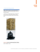
In addition to the SSA or SSG modules, the Tigo
Optimizer System requires Gateways and Manage-
ment Units (MMU) for proper operation.
For more information on the Tigo Optimizer System
please contact Tigo Energy at:
• www.TigoEnergy.com
• (USA) 1.888.609.8446
• (outside the US) +1.408.402.0802
• skype: support.tigoenergy
9.5 Silfab Module installation in Marine Applications
This section provides guidance of safe handling
and installation of Silfab PV modules between 50 to
500 meters to any salt water costal waterway
regarded as “near-coastal”. Improper care and
negligence to properly protect PV system as
recommended may potentially induce salt-mist
corrosion and accelerate electrical insulation losses
and galvanic corrosion. Any violation found will not
be covered under Silfab’s Limited Product and
Linear Performance Warranty. For further inquiries,
please contact Silfab’s Customer Service.
Important note: Disclaimer of liability
Silfab PV Modules have successfully passed IEC
61701:2011 – Level 5 Salt Mist Corrosion Test. Howev-
er, full protection against salt exposure is largely depen-
dent on multiple components of the PV system beyond
Silfab’s control. As such, Silfab can strongly recom-
mends to adhere to the installation procedure. If negli-
gence is found, Silfab cannot hold responsibility and
disclaim liability for any loss, damage, or expense arising
out from “near-coastal” installation.
13