
Silfab Installation Manual

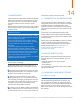

Product Modules in Series | Modules in Parallel
22 1
18 1
SLAxxM,
SSAxxxM,
SLA-X xxx
SLGxxxM,
SSGxxxM,
SLG-X xxx
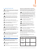
9. HANDLING OF MODULES
The Silfab modules are robust, but cells may
be subject to damage if the modules are improperly
handled or installed.
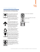
Wear protective gloves when handling and
installing the modules to protect against cuts and
burns.
Handle the module in a way that avoids
breakage or scratching of the glass or backsheet
and mechanical damage to any other part of the
module.
Do not carry the module by its cables.
Electric shock or damage to the module may result.
Do not drop sharp or heavy objects on
either surfaces of the module.
Do not subject the modules to any impact,
and do not flex them mechanically.
In the event of any damage to either the
front or the back of the module, dangerous electrical
hazards may exist, especially if the module is
connected in series to a string. Replace the module
immediately and take extreme caution when
handling.
Any modifications to the junction box cables
or connectors will void the module warranty. Any
attempted repairs or other tampering with the
junction box will void the warranty.
Do not step, walk or stand on the PV module.
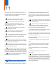
9.1 Electrical Connection
Do not connect or disconnect modules
under load! Danger! Risk of serious injury or death
from electric shock or electric arc flash!
Only connect modules with the same rated
current in series and modules with the same rated
voltage in parallel.
High hazardous voltage (several hundreds of
volts) may occur during installation. Consequently,
installation and maintenance of the modules, as well
as the connection to the main power supply, may only
be performed by authorized and qualified persons.
Under normal conditions, a PV module is likely
to experience conditions that produce more current
and/or voltage than reported at standard test condi-
tions. Accordingly, the values of Isc and Voc marked
on the module should be multiplied by a factor of 1.25
when determining component voltage ratings,
conductor ampacities, fuse sizes, and size of controls
connected to the module output.
The maximum system voltage rating is
1000V for TUV/IEC and 1000V for UL.
The maximum series fuse rating is 15A.
The bypass diodes are not over-current
protection devices. In the event of known or
suspected diode failure, installers or maintenance
providers should contact Silfab. Never attempt to
open the junction box!
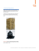
All connectors used with the Silfab modules
should be GZX model PV-GZX0601.
To obtain the desired system voltage,
modules are wired in series connection. The recom-
mended maximum series configuration must NOT
exceed the certified maximum system voltage stated
in the module spec sheet.
The recommended number of modules for series
connection can be found below:
10
Document Number: MAN-SFO-06 | SAFETY AND INSTALLATION MANUAL FOR PHOTOVOLTAIC MODULES