
Product Specifications

ELECTRICAL SPECIFICATIONS 370
Test Conditions STC NOCT
Module Power (Pmax) Wp 370 267
Maximum power voltage (Vpmax) V 34.95 31.68
Maximum power current (Ipmax) A 10.60 8.43
Open circuit voltage (Voc) V 41.75 37.84
Short circuit current (Isc) A 11.25 8.94
Module e iciency % 20.2% 18.3%
Maximum system voltage (VDC) V 1000
Series fuse rating A 20
Power Tolerance Wp 0 to +10
Measurement conditions: STC 1000 W/m² • AM 1.5 • Temperature 25 °C • NOCT 800 W/m² • AM 1.5 • Measurement uncertainty ≤ 3%
Sun simulator calibration reference modules from Fraunhofer Institute. Electrical characteristics may vary by ±5% and power by 0 to +10W.
TEMPERATURE RATINGS
Temperature Coeff icient Isc +0.064 %/°C
Temperature Coeff icient Voc -0.28 %/°C
Temperature Coeff icient Pmax -0.36 %/°C
NOCT (± 2°C) 45 °C
Operating temperature -40/+85 °C
SHIPPING SPECS
Modules Per Pallet: 26 or 26 (California)
Pallets Per Truck 34 or 32 (California)
Modules Per Truck 884 or 832 (California)
WARRANTIES
Module product workmanship warranty 25 years**
Linear power performance guarantee 30 years
≥ 97.1% end 1st yr
≥ 91.6% end 12th yr
≥ 85.1% end 25th yr
≥ 82.6% end 30th yr
CERTIFICATIONS
Product
ULC ORD C1703, UL1703, CEC listed***, UL 61215-1/-1-1/-2***, UL 61730-1/-2,
IEC 61215-1/-1-1/-2***. IEC 61730-1/-2***, CSA C22.2#61730-1/-2***, IEC 62716
Ammonia Corrosion; IEC61701:2011 Salt Mist Corrosion Certifed, UL Fire Rating: Type 2
MECHANICAL PROPERTIES / COMPONENTS METRIC IMPERIAL
Module weight 20kg ±0.2kg 44lbs ±0.4lbs
Dimensions (H x L x D) 1762 mm x 1037 mm x 35 mm 69.4 in x 40.8 in x 1.37 in
Maximum surface load (wind/snow)* 5400 Pa rear load / 5400 Pa front load 112.8 lb/ ^2 rear load / 112.8 lb/ ^2 front load
Hail impact resistance ø 25 mm at 83 km/h ø 1 in at 51.6 mph
Cells
120 Half cells - Si mono PERC
9 busbar - 83 x 166 mm
120 Half cells- Si mono PERC
9 busbar - 3.26 x 6.53 in
Glass
3.2 mm high transmittance, tempered,
DSM antirefl ective coating
0.126 in high transmittance, tempered,
DSM antirefl ective coating
Cables and connectors (refer to installation manual) 1350 mm, ø 5.7 mm, MC4 from Staubli 53.15 in, ø 0.22 in (12AWG), MC4 from Staubli
Backsheet High durability, superior hydrolysis and UV resistance, multi-layer dielectric fi lm, fl uorine-free PV backsheet
Frame Anodized Aluminum (Black)
Bypass diodes 3 diodes-30SQ045T (45V max DC blocking voltage, 30A max forward rectifi ed current)
Junction Box UL 3730 Certifi ed, IEC 62790 Certifi ed, IP67 rated
* Warning. Read the Safety and Installation Manual for mounting specifi cations and before handling, installing and operating modules.
** 12 year extendable to 25 years subject to registration and conditions outlined under “Warranty” at silfabsolar.com
*** Certifi cation anticipated May 2021.
PAN fi les generated from 3rd party
performance data are available for download
at: silfabsolar.com/downloads
Silfab - SIL-370 HC
No reproduction of any kind is allowed. Data
and information is subject to modifi cations
without notice. © Silfab 2020.
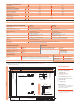
Side
Back View
Profile
40.8" [1037mm]
2.4" [60mm]
14" [356mm]
41.34" [1050mm]
14" [356mm]
8" [200mm]
39.25" [997mm]
53.15"[1350mm]
Drainage (x8)
Mounting Hole(x4)
Ø4.2mm (x2)
Grounding Hole
69.4" [1762mm]
1.4" [35mm]
0.3"[7mm]
0.5"[12mm]
0.6"
[15mm]
C C
1.4" [35mm]
1.4" [35mm]
0.06"[1.5mm]
240 Courtneypark Drive East
Mississauga ON L5T 2Y3 Canada
+1 905.255.2501
+1 905.696.0267
T
F
T
800 Cornwall Ave
Bellingham WA 98225 USA
+1 360.569.4733
info@silfabsolar.com
SILFABSOLAR.COM
SILFAB SOLAR INC.