
Network Card User's Manual
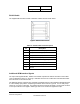


Page 16 silex SX-550 Evaluation Daughtercard
Hardware Configuration
Part Number 40183-101
Evaluation
Daughtercard
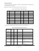
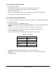
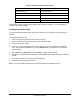
GPIO
CN210
GPIO
I/O Drive High/Low Description
9 50 O or I/O 6/6 mA LED_2 or used as a GPIO
1= off
0 = illuminated
10 51 O or I/O 6/6 mA LED_3 or used as a GPIO
1= off
0 = illuminated
43 O 6/6 mA SPI chip select
44 O 6/6 mA Ethernet PHY
1 = power down
0 = off (default)
47 O 6/6 mA Ethernet PHY
1 = not reset (default)
0 = reset#
52 I 6/6 mA PCI_LED2YP input
53 I 6/6 mA PCI Power Management Event#
input
54 O 6/6 mA PCI Clock
1 = clock off
0 = run# (default)
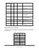
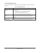
LEDs and General Purpose IO Signals
The LEDs are connected to the 10 GPIOs for easy viewing of signal activity. The first 7 GPIOs drive the
first 7 LEDs, D4 to D10. The last 3 GPIOs 8 to 10 drive LEDs D1 to D3. Logic 0 and 0 volts on GPIO_x
illuminates the LED.
Table 9 LED and GPIO Descriptions
GPIO LED
GPIO_1 D4
GPIO_2 D5
GPIO_3 D6
GPIO_4 D7
GPIO_5 D8
GPIO_6 D9
GPIO_7 D10
GPIO_8 D1 orange
GPIO_9 D2 yellow