
Network Card User's Manual


SX-550 Evaluation Daughtercard
Hardware Configuration
silex Page 15
Part Number 40183-101
General Purpose IO
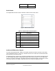
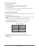
The GPIOs, located on JP7, can be used for controlling or monitoring OEM functions. External pull-ups
are recommended for customization.
N
OTE: GPIO 7 is fixed as a switch input and GPIO 8 is fixed as an LED output.
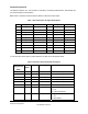
Table 7 General Purpose IO Signal Descriptions
Pin Signal Selectable Pin Signal Selectable
1 GPIO_1 Via JP3 2 GPIO_2 Via JP3
3 3.3V 4 GPIO_3 Via JP3
5 GPIO_4 Via JP3 6 GND
7 GPIO_5 Via JP3 8 GPIO_6 Via JP3
9 GPIO_7 10 3.3V
11 GPIO_8 12 GPIO_9
13 GPIO_10 14 GND
15
16 3.3V
17
18
19
20
To use the first 6 GPIOs, place a jumper between JP3 and JP4 for the specific GPIO.
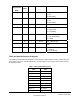
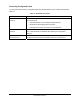
Table 8 General Purpose I/O Signal Description
Evaluation
Daughtercard
GPIO
CN210
GPIO
I/O Drive High/Low Description
1 2 I/O 6/6 mA Set as input or output
2 3 I/O 6/6 mA Set as input or output
3 4 I/O 6/6 mA Set as input or output
4 5 I/O 6/6 mA Set as input or output
5 6 I/O 6/6 mA Set as input or output
6 7 I/O 6/6 mA Set as input or output
7 48 I or I/O 6/6 mA Switch input
1 = off
0 = switch depressed
8 49 O or I/O 6/6 mA LED_1
1= off
0 = illuminated