
Network Card User's Manual
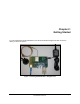

Page 10 silex SX-550 Evaluation Daughtercard
Hardware Configuration
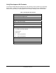
Part Number 40183-101
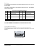
Function State Status
Yellow Blinking
Green Blinking
Wireless network data received, if wireless model
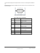
OEM Interface
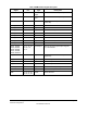
Table 3 describes the OEM interface pinout, J5, for the SX-550 Evaluation Daughtercard. Table 4
describes the OEM interface signal descriptions.
All input and output signals, except the differential signals, are 0 to 3.3 V logic signals.
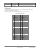
Table 3 OEM Interface Pinout
Pin Signal Pin Signal
1 TPRX+ 2 TPTX+
3 TPRX- 4 TPTX-
5 GPIO_7 6 GPIO_8
7 AVDD 8 +3.3VDD
9 UART0_RXD 10 GPIO_9
11 UART0_TXD 12 GPIO_10
13 GND 14 +3.3VDC
15 UART0_RTS 16 UART0_CTS
17 UART1_RTS 18 UART1_CTS
19 GND 20 GND
21 UART1_TXD 22 UART1_RXD
23 GND 24 RESET_N
25 SPI_CS 26 SPI_CLK
27 +3.3VDC 28 GND
29 GPIO_1 30 SPI_SDO
31 GPIO_2 32 SPI_SDI
33 +3.3VDC 34 GND
35 GPIO_3 36 GPIO_4
37 GND 38 GND
39 GPIO_5 40 GPIO_6