SX-550 WLAN Module Developer’s Reference Guide Part Number 40183-101 Revision D
© 2006 silex technology america, Inc.. All rights reserved. January, 2006 silex technology america SPECIFICALLY DISCLAIMS THE IMPLIED WARRANTIES OF MERCHANTABILITY AND FITNESS OF THIS PRODUCT FOR A PARTICULAR PURPOSE. silex shall not be liable for any errors contained in this manual or for any damages resulting from loss of use, data, profits, or any incidental or consequential damages arising from the use of SILEX products or services.
Contents About This Reference Guide ..................................................................................................................................... 1 Safety Precautions................................................................................................................................................. 1 Emissions Disclaimer.............................................................................................................................................
Chapter 6: Setting Configuration Parameters ........................................................................................................ 33 Factory Default Settings....................................................................................................................................... 33 Restoring Factory Default Settings .................................................................................................................. 34 Modify Basic Settings.......................
Figures Figure 1 Processor and Wireless LAN Radio PCB .................................................................................................. 3 Figure 2 Installing WLAN Module in Daughtercard .................................................................................................. 5 Figure 3 WLAN Module Inserted in Daughtercard ................................................................................................... 7 Figure 4 Antenna Connectors.................................
Table 25 GPIO Commands .................................................................................................................................... 41 Table 26 GPIO Trigger Commands........................................................................................................................ 42 Table 27 GPIO Transmit Commands ..................................................................................................................... 43 Table 28 Port Monitor Alert Commands .........
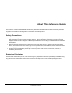
About This Reference Guide This reference guide provides detailed specifications, diagrams and additional information required to integrate the Ethernet and Wireless Serial Server Module in a product. The intended audiences are the developers and engineers responsible for the integration of the module in another product. Safety Precautions To prevent damage to the SX-550 module’s electronic circuit components, follow established ESD practices and procedures for handling static-sensitive devices.
Page 2 silex Part Number 40183-101 About This Reference Guide
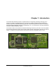
Chapter 1: Introduction The SX-550 WLAN Module provides a complete solution for integrating networking technology into a product. It includes an embedded processor, auto-sensing 10baseT/100baseTX Ethernet MAC/PHY, wireless chipset and embedded operating system with a full networking stack and drivers. The wireless high speed network interface conforms to the IEEE 802.11a, b, g, and h protocols. The radio is based on Conexant’s PRISM WorldRadio chipset.
Page 4 silex Part Number 40183-101 Introduction
Chapter 2: Getting Started You can install the SX-550 WLAN Module in the SX-550 Evaluation Daughtercard and connect the cabling, as shown in Figure 2.
Verify Development Kit Contents The SX-550 Evaluation Module Development Kit CAS-1000-I2C product consists of the components listed in Table 1. Please ensure that all materials listed are present and free from visible damage or defects before proceeding. If anything appears to be missing or damaged, please contact SILEX.
Installing the SX-550 WLAN Module To install the SX-550 WLAN module in the SX-550 Evaluation Daughtercard: 1. Using the 40-pin OEM header, plug the SX-550 WLAN Module in the SX-550 Evaluation Daughtercard and secure with screws, nuts and spacers. Figure 3 WLAN Module Inserted in Daughtercard 2. Plug the main antenna cable into the right top corner Main Antenna Connector on the card. If needed, plug the auxiliary antenna cable into the Auxiliary Antenna Connector.
3. Connect the magnetic antenna base cable to the antenna cable. 4. Connect the antenna to the base. 5. Connect one serial null-modem cable from the Serial Port 2 DB-9 connector on the evaluation daughtercard to a serial port on a personal computer or laptop. The PC or laptop acts as a console port for command line configuration and monitoring. 6. If an Ethernet LAN connection is required, plug a category 5 Ethernet cable into the RJ-45 jack.
Chapter 3: SX-550 Evaluation Daughtercard Hardware Configuration Monitoring Module Status You can monitor the module status using the yellow, green and orange LED status indicators on the monitor. Table 2 defines the default functions of the LED status indicators.
Function State Status Yellow Blinking Wireless network data received, if wireless model Green Blinking OEM Interface Table 3 describes the OEM interface pinout, J5, for the SX-550 Evaluation Daughtercard. Table 4 describes the OEM interface signal descriptions. All input and output signals, except the differential signals, are 0 to 3.3 V logic signals. Table 3 OEM Interface Pinout Pin Page 10 Signal Pin Signal 1 TPRX+ 2 TPTX+ 3 TPRX- 4 TPTX- 5 GPIO_7 6 GPIO_8 7 AVDD 8 +3.
Table 4 OEM Interface Signal Description Signal Pin Type Description TPRX+, TPRX- 1,3 Differential output Ethernet Transmit Data primary TPTX+, TPTX- 2,4 Differential input Ethernet Receive Data primary AVDD 7 Power Ethernet Power Output to transformer center tap UART0_RXD 9 Input Serial Port 1 Receive Data UART0_TXD 10 Output Serial Port 1 Transmit Data UART0_RTS 15 Output Serial Port 1 Request To Send UART0_CTS 16 Input Serial Port 1 Clear to Send UART1_RXD 22 Input Seri
Electrical Characteristics The power requirements, port pinouts, GPIO characteristics, cable connections and wireless operational modes are described below. Power Input Power to the SX-550 WLAN Module and Evaluation Daughtercard is supplied through the power jack, located at J4, at +5VDC ±10%. Use a +5VDC power supply with a minimum of 1 amp capacity. Power of +3.3VDC ±5% is input to the SX-550 WLAN Module via the OEM header, J5.
Serial Ports The two serial ports can be accessed with RS-232 signals, via the DB-9 connectors, or logic signals, via the 10-pin headers. The two logical serial port headers are located at JP2 and JP6. The serial ports provide four dedicated signals and three optional signals. The optional signals are configured using jumpers. Table 5 details the serial port signal descriptions.
To select the GPIO signals, place the jumper between JP3 and JP4. The GPIO signals are available at JP7 Standard serial RS-232 signals are available on the DB-9 connectors J2 and J3 for serial ports 1 and 2, as shown in Figure 8.
General Purpose IO The GPIOs, located on JP7, can be used for controlling or monitoring OEM functions. External pull-ups are recommended for customization. NOTE: GPIO 7 is fixed as a switch input and GPIO 8 is fixed as an LED output. Table 7 General Purpose IO Signal Descriptions Pin Signal Selectable Pin Signal Via JP3 2 GPIO_2 Via JP3 4 GPIO_3 Via JP3 1 GPIO_1 3 3.3V 5 GPIO_4 Via JP3 6 GND 7 GPIO_5 Via JP3 8 GPIO_6 9 GPIO_7 10 3.
Evaluation Daughtercard CN210 I/O Drive High/Low Description GPIO GPIO 9 50 O or I/O 6/6 mA LED_2 or used as a GPIO 1= off 0 = illuminated 10 51 O or I/O 6/6 mA LED_3 or used as a GPIO 1= off 0 = illuminated 43 O 6/6 mA SPI chip select 44 O 6/6 mA Ethernet PHY 1 = power down 0 = off (default) 47 O 6/6 mA Ethernet PHY 1 = not reset (default) 0 = reset# 52 I 6/6 mA PCI_LED2YP input 53 I 6/6 mA PCI Power Management Event# input 54 O 6/6 mA PCI Clock 1 = clock off 0 = run#
GPIO GPIO_10 LED D3 green RS-232 Cable The supplied DB-9 female-to-female null modem cable is wired as shown below.
OEM Interface Electrical Characteristics Table 11 OEM Signal Parameter Descriptions Parameter Symbol Condition Input high voltage Vih Input low voltage Vil Output high voltage Voh Ioh = 4mA Vol Iol = 4mA Voh Ioh = 6mA Vol Iol = 6mA Ii 0 < Vin < 3.3v Minimum Maximum 2.0▼ Unit Volts 0.7 2.4 Volts Volts UART0_TXD, UART0_RTS, UART1_TXD, UART1_RTS Output low voltage 0.4 Volts UART0_TXD, UART0_RTS, UART1_TXD, UART1_RTS Output high voltage 2.
Chapter 4: Using the SX-550 WLAN Module The SX-550 WLAN module provides a dedicated host processor and an industry-leading network protocol stack for connectivity to a traditional wired Ethernet or an 802.11a, b or g wireless local area network. The module is easy to configure with several management options, including an internal web browser interface and the Windows-based ExtendView configuration utility.
Using the Wired Ethernet Method To use wired Ethernet method: 1. Connect the Ethernet cable to the RJ-45 jack. This disables the wireless card. 2. Connect the power supply plug to the SX-550 Evaluation Daughtercard. 3. Power on the power supply. When a link is established, the yellow and green LEDs on the module should begin blinking. 4. Continue to the Access silex Console Interface section.
Generating Configuration Data You can generate and view the configuration data using the pushbuttons on the module as described in Table 13. Table 13 Pushbutton Functions Action Depress for less than 5 seconds Result Generates configuration data output on Serial Port 1 of the module. It can be viewed with a: Terminal emulator, such as Windows HyperTerminal.
Page 22 silex Part Number 40183-101 Using the SX-550 WLAN Module
Chapter 5: Accessing Configuration Parameters The SX-550 is equipped with a default configuration that works with most serial-to-Ethernet and wireless connections. You can modify the settings to suit your installation requirements by accessing: • ExtendView Utility • HTTP Pages Using Web Browser • Internal Command Console If using Microsoft Windows operating systems, the ExtendView Utility is the recommended method of configuring SX-550 modules on your network.
Table 14 ExtendView System Requirements Component Requirement -- VERIFY Personal Computer 133 MHz or higher Microsoft Windows Operating System 98SE, ME, 2000, XP or 2003 RAM Memory 64 MB or greater Hard Disk Space 10 MB or greater CD-ROM Drive The developer’s kit CD contains the ExtendView Utility software. In addition, you can download the software from the silex websites.
Using ExtendView Utility To start ExtendView: 1. On the Windows main page, select Start/Programs. 2. Select silex technology, then ExtendView. The ExtendView Utility displays. Figure 10 ExtendView Main Page You must create a view to determine which servers on your network will be discovered and how that information is displayed. During the initial start up of the utility, the New View wizard begins. 3. To continue, click Next. To ext, click Cancel. The New View window displays.
Figure 12 Create View with Default Settings 5. Click Finish. The ExtendView window displays a list of servers on the network. 6. Select the SX-550 module, then right click to display the menu. The default SX-550 module name is SDSxxxxxx where xxxxxx is the last six digits of the MAC address from the label located on the back of the SX-550 module.
7. Select Configuration. The Server Configuration window displays as shown in Figure 14. Figure 14 ExtendView Configuration Window 8. If no DHCP server exists, Extendview will prompt for a password before the configuration page displays. If you are unsure of the IP address, check with your network administrator. 9. If using a wireless SX-550 module, configure the wireless settings by selecting country or region for the region of operation.
To send configuration data to the serial device, press the Test button on the SX-550 module. The serial device should display or print the IP address assigned to the SX-550 module by your network DHCP service. If your network does not use DHCP, then the SX-550 module will have the default IP address of 192.0.0.192. Note: When using the SX-550 module wirelessly, verify you are communicating using AdHoc mode with the SSID configured as ‘serserv.’ 3. Enter the password. The default password is ACCESS.
• SX-550 Web Page Configuration Using Telnet Session To access using telnet: 1. Connect the SX-550 module’s Ethernet cable to the host computer. 2. On the Windows main page, select Start>Run. The Run window displays. 3. Type the following command, then click OK. telnet x.x.x.x where x.x.x.x is the IP address of the SX-550 module The default port is 23. 4. When the connection is established, press Enter. The # prompt displays. 5. Type the password (default is ACCESS), then press Enter.
Table 15 Port Settings Parameter Setting Bits per Second 115200 Data Bits 8 Parity None Stop Bits 1 Flow Control None 7. Press Return to display the Local prompt. To display the IP address, type Local> sh ip. The console displays the boot information, such as IP Address, Subnet Mask, IP Gateway, LPD Banner, LPD Retries, Boot Tries, Boot Method, Maximum Window, Timeout, Keepalive, Service, Port and TCP Port.
Any AT command received, except the listed commands, are acknowledged with OK status. This allows existing modem applications to transmit commands without causing an error. These include ATn, but not currently AT&n, AT%n, AT\n, where is a letter. Table 16 AT Commands Parameter Command Description Enter Command mode +++ If the string +++ is seen in data mode, with no characters sent for 1 second before or after, then command mode is entered.
Parameter Quiet mode Command ATQn Description If n = 1, no result codes are returned. If n = 0, result codes are returned to the local device. 0 is the reset default value. Verbose mode ATVn If n = 0 and not in quiet mode, result codes are returned in numerical form. If n = 1, results are returned as text. 1 is the reset default value. Table 17 Extended AT Commands Parameter Console pass through Command AT#C Description Passes the string to the server configuration console.
Chapter 6: Setting Configuration Parameters The SX-550 module is equipped with a default configuration that works with most serial-to-Ethernet and wireless connections. You can modify the settings to suit your installation requirements. ExtendView is the recommended method for setting configuration parameters. However, regardless of the method to access the configuration parameters, the method for modifying the parameters is virtually identical.
Parameter Ecport Description E-cable destination IP port number Settings Default Setting 9100 or set by user 9100 Restoring Factory Default Settings The factory default settings can restored at any time. Simply perform a cold reset by pressing and holding the module push button for more than five seconds. Modify Basic Settings To establish communication between the SX-550 module and a serial device, the settings must be identical for both devices.
Figure 17 Serial Settings Window 3. Configure the serial settings, as defined in Table 20. Table 20 Serial Setting Parameters Parameter Setting Mode Sets the line mode or serial port protocol. Character Bits RS-232 provides an interface between data terminal equipment and data communications equipment employing serial binary data interchange over a wired connection with a maximum range of 50 feet (16.5 meters).
Parameter Stop Bits Setting Sets the number of extra bits that mark the end of a unit of transmission. Values are: 1 (default), 2 Flow Control Manages data flow between computers or devices so data can be handled at an efficient pace. Values: None (default), Xon, Xoff, CTS/RTS 4. To accept changes, click OK. To cancel, click Cancel. For additional help, click Help. NOTE: You can configure the same settings using the Web Page configuration.
2. Verify the settings, as defined in Table 21. Table 21 TCP/IP Settings Parameter IP Address Resolution Setting Sets the exchanges among network interfaces connected to an Ethernet media segment and maps IP address to Ethernet addresses, Media Access Control (MAC) addresses and hardware addresses. The Set Permanent radio button sets the IP address permanent. The IP address must follow the format XXX.XXX.XXX.XXX, where each XXX is a number between 0 and 255.
Figure 20 Advanced TCP/IP Configuration Window 5. Configure the settings, as defined in Table 22. Table 22 TCP/IP Configuration Settings Parameter Setting TCP Connection Timeout Sets the timeout and reset values for the TCP connections Unsolicited ARP Blocks or broadcasts unsolicited ARP DNS Sets the DNS addresses 6. To accept changes, click OK. To cancel, click Cancel. For additional help, click Help. NOTE: You can configure the same settings using the Web Page configuration.
Configure Simple Network Management Protocol The SX-550 module contains a Simple Network Management Protocol (SNMP) agent that collects and stores management information for network managers using standard SNMP commands. The management information is referenced as a hierarchically organized database called a Management Information Base (MIB). To prevent naming conflicts, all of the manageable features of all products from all vendors are arranged in a single tree structure.
Figure 21 SNMP Traps 2. Configure the settings as defined in Table 24. Table 24 SNMP Trap Settings Parameter Setting Protocol Sets the protocol Trap Destination – TCP/IP Address Sets the IP address for the trap destination Port Sets the port location Port Traps Sets the port traps GPIO Traps Sets the GPIO traps 3. To accept changes, click OK. To cancel, click Cancel. For additional help, click Help.
Table 25 GPIO Commands Command Description SHOW GPIO DIR Shows current direction setting of GPIO lines SET GPIO DIR IN|OUT Sets GPIO Direction In/Out GPIO # = {1|2|3|4|5|6|7|8} Example: Local> show gpio dir GPIO Direction -------------1 [OUT] 2 [IN] 3 [IN] 4 [IN] 5 [SPCL] 6 [SPCL] 7 [SPCL] 8 [SPCL] Local> set gpio dir in 1 Local> set gpio dir out 2 Local> show gpio dir GPIO Direction -------------1 [IN] 2 [OUT] 3 [IN] 4 [IN] 5 [SPCL] 6 [SPCL] 7 [SPCL] 8 [SPCL] Setting Configuration Paramete
Command Description SHOW GPIO SPECIAL Shows functional mode of GPIO lines SET GPIO SPECIAL ENA/DIS Sets GPIO special function mode GPIO # = {1|2|3|4|5|6|7|8} Example: Local> show gpio special GPIO Special Functions ----------------------GPIO #1 is special GPIO #2 is normal GPIO #3 is special GPIO #4 is special GPIO #5 is special GPIO #6 is special GPIO #7 is special GPIO #8 is special Local> set gpio special disable 1 Local> set gpio special enable 2 Local> show gpio special GPIO Special Fun
Command Description Local> set gpio trig 0 2 Local> show gpio trig GPIO Trigger Conditions ----------------------trig if GPIO #1 is 1 trig if GPIO #2 is 0 GPIO #2 is set for OUTPUT GPIO #3 is set for OUTPUT Table 27 GPIO Transmit Commands Command SHOW GPIO TRANsmit SHOW GPIO TRANsmit Description Displays email or web page strings assigned to GPIO triggers trig # = 0 to 7 SET GPIO TRANsmit Sets transmit string corresponding to trigger condition trig # = 0
Configuring Serial Port Monitor Alert and Trap Configuration The SX-550 module can be configured to scan and compare the data received on the serial port to userdefined strings. A match with a string can be a source for SNMP traps and/or email alerts. The match strings and corresponding email or web page message strings are configured from the Internal Configuration Console interface. Table 28 describes the Monitor Alert and Trap Configuration Commands.
Table 29 TRIGMON Commands Command Description SHOW PORT S1 TRIGXMT Shows email or web page strings associated with TRIGMON index numbers SET PORT S1 TRIGXMT Assigns email or web page string to specified TRIGMON index number Index # = 0 to 7 Example: Local> show port s1 trigxmt Index # -----0: Xmit String --------------xmit string 0 <<< default msg string Local> set port s1 trigxmt 0 The trigger string was seen! Local> show port s1 trigxmt Index # -----0: Xmit String ------------
Chapter 7: Designing with the SX-550 OEM Header Interface Table 30 describes the OEM header interface pinout for the SX-550 WLAN Module. Table 31 describes the OEM interface signal descriptions. All input and output signals, except the differential signals, are 0 to 3.3 V logic signals. Table 30 OEM Header Interface Pinout Pin Signal Pin Signal 1 TPRX+ 2 TPTX+ 3 TPRX- 4 TPTX- 5 GPIO_7 6 GPIO_8 7 AVDD 8 +3.3VDD 9 UART0_RXD 10 GPIO_9 11 UART0_TXD 12 GPIO_10 13 GND 14 +3.
Table 31 OEM Interface Signal Description Signal Pin Type Description TPRX+, TPRX- 1,3 Differential Output Ethernet Transmit Data primary TPTX+, TPTX- 2,4 Differential Input Ethernet Receive Data primary AVDD 7 Power Ethernet Power Output to transformer center tap UART0_RXD 9 Input Serial Port 1 Receive Data UART0_TXD 10 Output Serial Port 1 Transmit Data UART0_RTS 15 Output Serial Port 1 Request To Send UART0_CTS 16 Input Serial Port 1 Clear to Send UART1_RXD 22 Input Ser
Antenna Connectors The SX-550 WLAN Module has two SMT Ultra-miniature coaxial connectors (U.FL). Table 32 describes the connector types. For single antenna use, connect to the main antenna connector, as shown in Figure 22 . For diversity antenna use, connect to both the main and auxiliary connectors. Figure 22 Main and Auxiliary Antenna Connectors Table 32 Antenna Connector Types Parameter Description Connector Type SMT Ultra-miniature Coaxial Connector (U.FL) Connector Size Maximum height of 2.
Ethernet PHY The Ethernet PHY is located on the processor card. The manufacturer is Davicom and the part number is DM9161AE. For additional information on the layout of the transformer and RJ-45 jack, refer to the Davicom website at www.davicom.com.tw. 2 1:1 1 7 2 3 4 4 40-pin OEM Header Transformer 5 1:1 6 7 1 7 3 RJ46 8 Figure 23 Circuit Diagram with Transformer Transformer Specification Table 33 and Table 34 detail the magnetic specifications and manufacturer sources.
Table 34 10/100M Magnetics Manufacturers Manufacturer Part Number Pulse Engineering PE-68515, H1102 YCL PH163112, PH163539 Halo TG110-050N2, TG110-LC50N2 Bel Fuse S358-5999-W2 Bothhand TS6121CX, LU1S041CX, TS61210, I6ST8515, 16ST1066 GTS FC-618SM General Purpose I/O Interface Table 35 details the GPIO interface. The first 10 GPIOs are user-configurable as either input or output. GPIOs 48 to 51 have default uses, but can be user configured.
40-Pin Header GPIO I/O Drive High/Low Description CN210 GPIO 44 O 6/6 mA Ethernet PHY 1 = power down 0 = off (default) 47 O 6/6 mA Ethernet PHY 1 = not reset (default) 0 = reset# 52 I 6/6 mA PCI_LED2YP input 53 I 6/6 mA PCI Power Management Event# input 54 O 6/6 mA PCI Clock 1 = clock off 0 = run# (default) Power Power is input to the SX-550 WLAN Module using the 40-pin OEM Header. Required voltage is 3.3VDC ± 5%. At full power, the current consumption is 950mA.
Chapter 8: Product Specifications Table 36 Product Specifications Component Specifications Model SX-550 WLAN Module Processor Cavium NITROX Soho CN210 RAM Memory 16 Mbytes SDRAM. Processor Speed 167 MHz at full power Interfaces Supported Serial: RS-232 w/ external transceivers Ethernet: 10/100BaseT using RJ-45 8-wire jack Serial Peripheral Interface Table 37 Radio Performance Specifications Parameter Specifications Radio Emission Type Complies with IEEE 802.
Parameter Specifications Data Rate 54 Mbps with fallback rates of 48, 36, 24, 18, 12, 11, 9, 6, 5.5, 2, and 1 Mbps Security WEP Encryption: 64/128 bits TKIP, AES Media Access Protocol Carrier Sense Multiple Access with Collision Avoidance (CSMA/CA) with ACK architecture, 32 bits MAC-layer. Antenna Connector Type 2 SMT ultra-miniature coaxial connectors Operating Voltage 3.
Power Output high band (802.11a) 9 Mbps 15 16.1 21 12 Mbps 14 15.6 20 18 Mbps 14 15.6 20 24Mbps 13 14.8 19 36 Mbps 13 14.8 19 48 Mbps 8.5 10.9 15 54 Mbps 8.5 10.9 15 Receiver Sensitivity (Production Specification) Test Conditions: Supply Voltage (Vcc) = 3.3V, Ambient Temperature = 25ºC Frequency Range (Bands) Modulation Rate Transmitter Power Output low 1Mbps (8%PER) band (802.11b) (8%PER) 2 Mbps 5.
(10%PER) 54 Mbps -68 -70 / -88 -90 / -86 -88 / -85 -87 / -82 -84 / -78 -80 / -74 -76 / -69 -71 / -67 -69 / (10%PER) Transmitter Power Output high 6 Mbps (10%PER) band (802.11a) (10%PER) 9 Mbps 12 Mbps (10%PER) 18 Mbps (10%PER) 24 Mbps (10%PER) 36 Mbps (10%PER) 48 Mbps (10%PER) 54 Mbps (10%PER) TCP Port Connections The SX-550 module supports port connections over TCP/IP using raw TCP ports only. Table 38 describes the TCP ports allocations.
Appendix A: Console Commands The following tables describe the console commands available from the internal command console. Access the command console through the serial port (J1), console port (JP1) or Ethernet port using a Telnet session. Wireless and Network Security Commands The following group of commands configures network parameters.
Command SH NW AUTH Description Shows wireless authentication type The default value is 11. Value is ignored in Infrastructure mode. Sample output: Authentication type= OPEN SYSTEM SET NW CHannel Sets WLAN ad-hoc channel number Sample output: SET NW CHannel n n = 1-11 SET NW ENC Sets WLAN Encryption Mode. Supported modes are None, 64 bit WEP, 128 bit WEP, and TKIP (WPA). The default value is Disable.
Command Description SH NW RADio Shows the selected radio mode of operation Sample output: Radio mode is 802.11b SET NW SPeed Sets maximum WLAN speed The default value is 11. Sample output: SET NW SPeed n n = 1,2,5.5 or 11 SH NW SPEED Show the maximum wireless data speed in megabits per second Sample output: Speed = 11 SET NW SSid Sets WLAN SSID The default value is printer. Sample output: SET NW SSid User defined CL NW SSid Clears SSID value and allows the server to connect to any AP.
Command Description TX Fragments: 0 TX Unicast octets: 0 TX Multicast octets: 0 TX Deferred: 0 TX Single retry frames: 0 TX Multiple retry frames: 0 TX Retry limit exceeded: 0 TX Discards: 0 RX Unicast frames: 0 RX Multicast frames: 0 RX Fragments: 0 RX Unicast octets: 0 RX Multicast octets: 0 RX FCS errors: 0 RX Discards no buffer: 0 TX Discards wrong SA: 0 RX Discards WEP undecr: 0 RX Msg in msg fragments: 0 RX Msg in Bad msg fragments: 0 SET NW CERTCN Sets EAP Common Name The default value is null.
Command SET NW CERTEXP Description Sets EAP Certificate Exponent value The default value is 10001 Hex. Sample output: SET NW CERTEXP User defined SH NW CERTEXP Shows the value of the certificate exponent The deprecated command SH NW TTEXP also returns this value Sample output: 65537 (10001h) SET NW CERTKEY Sets EAP root key Sample output: SET NW CERTKEY SET NW ID Sets authentication User ID This can include the realm separated by @. The default value is anonymous.
Command Description Sample output: SET NW REALM SH NW REALM Shows the realm associated with the authentication ID, if applicable. The default value is null (blank) string. The deprecated command SH NW TTRE also returns this data. Sample output: somewhere SET NW WPAGROUPSH NW WPAAUTO Enable or disable WPA group key mode. If enabled, group keys can be used for data link encryption. The default value is disabled.
Command SET NW WPATRACE Description Sets WPA trace level. This command is for diagnostic purposes only. The default value is 0 or disabled. Sample output: SET NW WPATRACE nn Port Commands Table 40 Port Commands Command SH PORT Description Shows port parameters Sample output: Port Q-Size *S1 XON/XOFF RS232 SET PORT Type 0 Attributes serial 115200 N 8 1 Sets port parameters. The commands are dependent on the port type. CLEAR PORT S1 JOB Aborts the active job on the port.
Command Description Sample output: SET PORT S1 SPEED SET PORT S1 STOP Sets serial port stop bits per character The default value is 1.
Command SET SNMP LOCation Description Sample Output Sets system location string The default value is null.
Command Zero Description Sample Output Clears and resets the network statistic counters Service Commands Table 42 Service Commands Command SET SERVI BOT Description Sets beginning of transmission (BOT) string index for service The default value is 1. Sample output: SET SERVI BOT SET SERVI EOT Sets end of transmission (EOT) string index for service The default value is 1.
Command Description Sample output: SET SERVI FRM SET SERVI FRS nn Sets filter 1 text replacement replace string index. If the index is zero, the default string of (carriage return-line feed) is used. The default value is 0. Sample output: SET SERVI FRS SET SERVI IP nn Enables or disables IP based jobs such as lpd, raw tcp and ftp, on the service The default value is enabled for service 1 and 2, disabled for all others.
Command Description [service_num] provided, parameters for all services are displayed. The command SH SERVI displays the same data as SHOW SERVI SUM. String Commands Table 43 String Commands Command SET STRing Description Set service string table entry String 1 to11 cannot be set or changed.
Command Description 3 Text to PostScript 4 PostScript Tagged Binary 5 DC1 Special TCP/IP Commands Table 44 TCP/IP Commands Command SET IP ACcess Description Allows or prevents access to a block of remote addresses The default value is empty list. Sample output: SET IP ACcess [EN | DI | ALL] aa.bb.cc.dd {MAsk ee.ff.gg.hh] SET IP RANge Allows or prevents access to a range of remote addresses The default value is empty list. Sample output: SET IP RANge [EN | DI | ALL] aa.bb.cc.dd {MAx ee.ff.gg.
Command Description The default value is 3. Sample output: SET IP BOot SET IP ENable n Enables or disables all IP based protocols The value is Enable. Sample output: SET IP [ENable | DIsable] SET IP FTIme Sets IP timeout If enabled, the IP timeout is measured in seconds. If disable, the IP timeout is in minutes. The default value is Disable. Sample output: SET IP FTIme [ENable | DIsable] SET IP FTP Enables or disables FTP protocol The default value is Enable.
Command Description Sample output: SET IP PRObe SET IP RARp [ENable | DIsable] Enables setting of default router and/or subnet mask based on RARP IP address set The default value is 0. Sample output: SET IP RARp nn nn: 0=both 1=no subnet, SET IP REtry 2=no router, 3=neither Enables or disables LPD retry on incomplete job The default value is Disable. Sample output: SET IP REtry SET IP ROuter [ENable | DIsable] Sets default router address The default value is 0.0.0.0.
Command Description SET IP TImeout SET IP WIndow n Sets TCP maximum window size in bytes The default value is 10240. Sample output: SET IP WIndow SH IP nn Shows TCP/IP related parameters The default value is Sample output: IP is enabled IP address 192.0.0.192 Boot tries 3 Subnet mask 0.0.0.0 Boot method AUTO IP Gateway 0.0.0.
Command Description This command is used for diagnostic purposes only. The default value is Disable. Sample output: SET LOAd (ENable | DIsable ] SET LOAd HOst Sets the node name of the Netware boot host. This command is used for diagnostic purposes only. The default value is null>\ Sample output: SET LOAd HOst SET LOAd IP Sets source computer IP address for TFTP get operation. The default value is 0.0.0.0. Sample output: SET LOAd IP SET LOAd SOftware aa.bb.cc.
Miscellaneous Commands Table 47 Miscellaneous Commands Command Description SET DEFAULT Set parameters to factory defaults EXIT This command exits the current configuration console session. SH FATal Shows fatal error log, if fatal errors exist. CL FATal Clears the fatal error log INIT Instructs the server to execute a soft reset when the next exit command is executed.
Appendix B: Engineering Drawings Antenna Cable Assembly Figure 24 Antenna Cable Assembly Table 48 Electrical Performance Parameter Value Impedance 50 ohms Frequency Range 0 to 5 GHz Working Voltage 6O VAC maximum Dielectric Withstanding Voltage 20 DVAC maximum Insulator Resistance 500 megohms minimum silex Part Number 40183-101 Page 74
Figure 25 Electrical Specifications for Antenna Figure 26 Connector Specifications Engineering Drawings silex Part Number 40183-101 Page 75
Table 49 Electrical Specifications Parameter Page 76 Value Antenna Type Dipole Swivel Antenna Frequency Range 2.4 to 5.8 GHz Impedance 50 Ohms Gain 2.4 GHz < 2.0 dBi 5.8 GHz < 0 dBi VSWR ≤ 2.
silex technology america, Inc. www.silexamerica.