Multicast Video Distribution System MVDS X-1 Installation / User's Guide
Introduction Thank you very much for purchasing Silex's MVDS X-1, the Multicast Video Distribution System (this product). This manual provides how to setup and use this product. About notation - Copying all or a part of this manual without our permission is prohibited. - The contents of this manual may be changed without advance notice. - Please note that the actual screens may vary from the examples in this manual. This can be caused by different versions of operating systems on the PC, upgrades, etc.
Index Product Overview..................................................... 1 1.1 About this product ........................................................................................2 1.2 Specification.....................................................................................................4 1.2.1 Hardware specification.....................................................................................................................4 1.2.2 Software specification .........................
Monitor and Maintenance ..................................... 33 3.1 Front panel..................................................................................................... 34 3.1.1 Menu structure and how to use it ............................................................................................. 34 3.1.2 Functions available in each menu............................................................................................. 36 Initial screen (Level:0)................................
1.
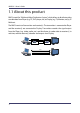
MVDS X-1 User's Guide 1.1 About this product MVDS stands for "Multicast Video Distribution System", which allows to distribute video or audio data from Player (e.g. PC, DVD player, etc) to Display (e.g. TV, Monitor, etc) by IP Multicast. The MVDS consists of transmitter and receiver(s). The transmitter is connected to Player and the receiver(s) are connected to Display. Transmitter encodes the signal output from the Player (e.g. video, audio, etc.
1.Product Overview Feature Video and Audio control - Adopts JPEG2000 codec.
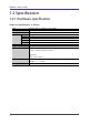
MVDS X-1 User's Guide 1.2 Specification 1.2.1 Hardware specification Hardware specification is as follows: CPU RAM ROM Interface Video Audio Serial Ethernet Wireless Power LCD LED Push Switch Rotary Switch 4 TOSHIBA TX4939 400MHz (32/64bit MIPS) 128MB DDR 8MB Analog RGB D-SUB15 x 1 16bit Stereo line in / out (Mini Jack) RS-232C (D-SUB9) x 1 10BASE-T/100BASE-TX Auto detection (RJ-45) x 1 IEEE802.
1.Product Overview FCC Notices This equipment has been tested and found to comply with the limits for a Class B digital device, pursuant to Part 15 of the FCC Rules. These limits are designed to provide reasonable protection against harmful interference in a residential installation. This equipment generates, uses, and can radiate radio frequency energy and, if not installed and used in accordance with the instructions, it may cause harmful interference to radio communications.
MVDS X-1 User's Guide 1.2.2 Software specification Software specification is as follows: Protocol TCP/IP Network Layer FLDP ARP , RARP , IPv4 , ICMP Multicast : IPv4 Organization Local Scope 239.192.0.
1.Product Overview 1.2.3 Interface specification Interface specification is as follows: Video Interface Codec Resolution Flame rate Configuration Others Analog RGB (15pin Dsub) JPEG2000 1280 x 768 pixel (WXGA) 30 fps (MAX) Video Adjustment(Contrast , Bright , Position etc…) Startup screen, Stop signal screen, Maintenance screen (Display a still image specified in each mode.
MVDS X-1 User's Guide 1.2.4 Notes on the radio wave Do not use this product near the following equipment or places. The following equipment may use the same band. If you use this product near this equipment, the radio waves from this product and the following devices may interfere with each other. - Microwave, scientific instruments, pacemaker or other medical equipment. - Licensed radio station in a factory. - Small power radio station (a non-licensed radio station).
1.Product Overview 1.3 Network composition A MVDS network is composed of one MVDS transmitter and 32 MVDS receivers (at maximum). In each group, a video or audio data are distributed in multicast (or unicast). As for network interface, both Wired and Wireless LAN ports are supported. Since MVDS transmitter and receivers exchange their status each other regularly, you can easily install and configure this product as well as support various network environment.
MVDS X-1 User's Guide Wireless system - Network composition for Ad-Hoc mode The player (e.g. PC or DVD player, etc.) outputs data (e.g. video, audio, serial data, etc.) to MVDS transmitter. The transmitter captures and sends them to the MVDS receivers being connected to the transmitter in Adhoc mode. AV Cable Wireless (IEEE802.11a/g) { Network composition for wired connection The player (e.g. PC or DVD player, etc) outputs data (e.g. video, audio, serial data, etc.) to MVDS transmitter.
1.Product Overview Network composition for wired/wireless connection mix If the wired/wireless system are mixed, you can support wider variety of environment. AV Cable Ethernet (100Base, PLC) Wireless (IEEE802.
MVDS X-1 User's Guide 1.4 Parts and function The name of each part and the function are explained below: Front Transmitter Push button MENU + SET 12 Description Go into LCD menu from initial screen. Return to initial screen from LCD top menu. Go back to higher level in LCD menu. Start a factory default configuration when this button and [SET] button are pushed together while turning on this product. Return to previous option in LCD menu. Select a value to set. Move to next option in LCD menu.
1.Product Overview Receiver Push button MENU + SET Description Start a factory default configuration when this button and [SET] button are pushed together while turning on this product. Not use. Not use. Start a factory default configuration when this button and [MENU] button are pushed together while turning on this product. LED (both Transmitter and Receiver) LED POWER STATUS WIRELESS ETHER Description OFF: Powered off or being on boot process.
MVDS X-1 User's Guide Back Both Transmitter and Receiver Part DCIN 15V1A ETHER RS232C AUDIO ANALOG RGB Antenna Description AC connector (15V 1A) * In case of X-1ER, AC power can be supplied via internal DC connector. Ethernet interface (RJ45) Serial interface (9pin Male) Audio interface (3.5mm mini) RGB interface (D-Sub15pin) SMA Connector (Connect the antenna to either or both of the connectors.
2.
MVDS X-1 User's Guide 2.1 Before you begin This section explains the necessary actions that should be taken before you connect and setup this product. 2.1.1 Necessary items Please prepare the following items. MVDS Transmitter ( X-1T ) MVDS Receiver ( X-1R ) PC (used for setup) Player Monitor Speaker VGA cable Audio cable LAN cable (used for setup) Antenna Configuration Software 16 One transmitter is required. As many receivers as you need for your environment.
2.Installation 2.1.2 Create environment for setup The first step is to connect the cables to the MVDS transmitter and receiver, and to the player, monitor(s) and PC. All the configuration can be performed via a wired LAN network. 1. Connect the LAN cables Connect the MVDS transmitter and receiver(s) to the PC using LAN cables. 2. Connect the VGA cables Connect the player to the MVDS Transmitter, and connect the monitor(s) to the receiver(s). 3.
MVDS X-1 User's Guide An example MVDS installation is shown below: Display Player VGA Cable Audio Cable VGA Cable Transmitter Receiver LAN Cable PC 18 Audio Cable
2.Installation 2.2 Configure this product When the cable connections and power on are completed, configure the network settings and adjust the screen images for the MVDS transmitter and receivers. 2.2.1 Assign IP address To simplify the configuration process, the MVDS transmitter and receivers support automatic configuration of the IP address. By default, they attempt to load an IP address via DHCP when powered on.
MVDS X-1 User's Guide 3. Select the MVDS transmitter or receiver that you wish to configure. From the top menu, click Configuration - Set IP address. 4. Configure a unique IP address that is not used by other network devices. (Example: 10.3.0.1) 5. Repeat this process and enter a unique IP address into each of the MVDS transmitters and receivers.
2.Installation 2.2.2 Configure via Web browser After you have assigned the IP address for each MVDS transmitter and receiver, you can configure these devices using a PC with any standard web browser. For each MVDS transmitter and receiver, access the Web page using the IP address you have configured into the device. By default the user name is "root" and no password is set. To view the IP address of the transmitter and the receivers, you can use the Admin Manager program.
MVDS X-1 User's Guide Host name / Password configuration Configure Host Name and Password. - Be sure to set a password, especially if you are using the MVDS with a public network. TIP In factory default, the last six hexadecimal digits of the Ethernet MAC address is used as the host name of the MVDS transmitter and receiver(s). You can change the host name if desired, but make sure that is a unique name.
2.Installation Network configuration * Required for both Transmitter and Receivers Configure the IP address and wireless settings. Select Network under Configuration in the Web page. TIP - The MVDS transmitter and receivers operate without the need to manually configure an IP address as they supports Auto IP function. - It is impossible to broadcast a movie across a router.
MVDS X-1 User's Guide Example: The following are the sample settings to use this product in AdHoc mode. Interface Mode SSID Ch.
2.Installation Adjusting a screen image (at transmitter) Connect to the web page of the transmitter to adjust a screen image appropriate for the player. If you are sure of what value to set for screen image, click Video/Audio/Data under Configuration and configure each setting. If you are not sure what values to set, you can use the auto-adjustment feature to automatically adjust the screen image. The use of the auto-adjustment function is described below: 1.
MVDS X-1 User's Guide 5. Click Video/Audio/Data under Configuration and adjust the settings such as PHASE_CC, etc. to make the image quality better.
2.Installation Adjusting a screen image (at receiver(s)) TIP - You normally do not have to adjust a screen image at the receivers since the monitor will automatically make adjustments. 1. If adjustment is necessary, go to the Web page of the transmitter. Click Video/Audio under Tools and click the Start button next to Maintenance screen mode to switch to maintenance mode and output the maintenance screen to the receivers. The MVDS will automatically adjust the image quality and position, etc.
MVDS X-1 User's Guide 2.3 Hardware installation 2.3.1 Connect to a wired network To configure this product in a wired network, connect the transmitter and receivers via Ethernet HUB.
2.Installation 2.3.2 Connect to a wireless network Below is a sample connection to install this product outdoors. Select the antenna according to your location status, distance from the receiver or layout.
MVDS X-1 User's Guide Vertical convergence angle and minimum distance Every 'high-gain' antenna has vertical and horizontal selectiveness. The narrower the coverage, the higher the possible gain. However, this selectiveness also creates 'blind spot' in close range, especially if antennas located in different height.
2.Installation Vertical coverage and Line-of-sight From a vertical convergence point of view, less height difference is better to minimize distance problems. However, it also creates more Non-Line-Of-Sight (NLOS) problems. In this diagram, the other side of the office building could not covered by single TX antenna, so another TX set needs to be provided if there are other stations there.
MVDS X-1 User's Guide 32
3.
MVDS X-1 User's Guide 3.1 Front panel The MVDS transmitter has a LCD which provides the operating status and configuration for transmitters. Use the push buttons to the right of LCD ( MENU, -, +, SET ) to switch the panel menu as well as change the settings. 3.1.1 Menu structure and how to use it The LCD menu has the structure below. "Level 0-3" at the top of this diagram indicate the hierarchy level.
3.Monitor and Maintenance Each menu can be switched by pushing the push buttons to the right of LCD. To switch the menu levels, use [MENU] and [SET] buttons. To switch the options in the same level, use [ + ] and [ - ] buttons. The menu transition diagram is as below.
MVDS X-1 User's Guide 3.1.2 Functions available in each menu This section explains the functions available in LCD menu. Initial screen (Level:0) This screen is always displayed while this product is turned on. When this product is running properly, the model name and operating status are shown in the upper line and lower line respectively. When an error occurs or the firmware of this product is being updated, operating status is displayed in both upper and lower lines.
3.Monitor and Maintenance SERVICE ACTIVITY Shows the service status for each data transfer. SERVICE ACTIVITY (sample) SERVICE:VIDEO ACTIVE 1280x768 Selected menu Current status of the selected menu Menu options and status Menu VIDEO Description Status Displays a service status for ACTIVE ****x*** video data transfer. NO SIGNAL ACTIVE STEREO AUDIO Displays the service status for audio data transfer. WAIT VIDEO SYNC SERIAL Displays the service status for READY serial data transfer.
MVDS X-1 User's Guide CONNECTION STAT Shows a network status. CONNECTION STAT (sample) CONN:ETHERNET LINK 100Mb/Full Selected menu Current status of the selected menu Menu options and status Menu ETHERNET Description Status LINK 100Mb/Full LINK 100Mb/Half Show the Ethernet link status. LINK 10Mb/Full LINK 10Mb/Half NOT CONNECTED CONNECTED CH:** NOT CONNECTED WIRELESS Show a wireless link status. NOT AVAILABLE DISABLED RTP LINK 38 Show the link status in RTP level.
3.Monitor and Maintenance DEVICE INFO Shows the device information. DEVICE INFO (sample) DEV:HOST NAME TX012345 Selected menu Current status of the selected menu Menu options and status Menu HOST NAME IP ADDRESS MAC ADDR F/W VERSION FPGA VER. Information displayed in the lower line Show the host name. Show the IP Address. Show the Mac Address. Show the firmware version. Show the FPGA version.
MVDS X-1 User's Guide ADMIN MODE MENU Part of settings can be configured, referred and maintained through ADMIN MODE MENU. This menu has a hierarchic structure below.
3.Monitor and Maintenance To enter into LEVEL2 in ADMIN MODE MENU, the PIN CODE is required (In the factory default setting, the PIN CODE is "0000"). PIN CODE entry screen ADMIN:PIN CODE PIN CODE? 0 _ _ _ Enter the PIN CODE. To enter the PIN CODE, select each number by pushing [ + ] and [ - ] buttons and save it by pushing [SET] button. If a correct PIN CODE is entered, configuration menus are displayed.
MVDS X-1 User's Guide WIRELESS CONFIG Shows or Changes the wireless LAN settings. WIRELESS CONFIG (sample) WIRELESS I/F ENABLE Menu WIRElESS I/F WIRELESS MODE SSID CH AUTO SEARCH Selected menu Current setting of the selected menu Information Displays whether the wireless LAN setting is enabled or disabled. Displays a wireless LAN mode (AdHoc/Infra.). Displays the SSID. Displays or Enables/Disables the channel auto-search function setting.
3.Monitor and Maintenance VIDEO CONFIG Shows or Configures the video settings. VIDEO CONFIG (sample) CAPTURE GAIN * R 128 G 128 B 128 Menu AUTO CONFIG Selected menu Current setting of the selected menu Information Starts the auto-adjustment for image parameters. By pushing [SET] button, you can switch to the auto-adjustment screen. Push [ + ] and [ - ] buttons to select [OK] (the current setting is enclosed with [ ]). Push [SET] button to start auto-adjustment. VGA CONFIG CANCEL [ OK ] Select [OK].
MVDS X-1 User's Guide VIDEO CONFIG Menu CAPTURE GAIN Information Displays or Configures the Gain value (R/G/B). You can switch to the configuration screen by pushing [SET] button. CAPTURE GAIN * R 128 G 128 B 128 s CAPTURE OFFSET Set the value in the order of R -> G -> B. Select a value by pushing [ + ] and [ - ] buttons and determine it by pushing [SET] button. When one value is determined, the cursor will move to the other. When the cursor came to "s", push [SET] button to save the settings.
3.Monitor and Maintenance SERIAL CONFIG Shows the serial settings. SERIAL CONFIG (sample) BAUD RATE (bps) 19200 Menu BAUD RATE (bps) BIT LENGTH STOP BIT PARITY FLOW CONTROL DATA TIMEOUT Selected menu Current setting of the selected menu Information Displays a baudrate. Displays a bit length. Displays a stop bit. Displays a parity bit. Displays a flow control setting. Displays a serial input timeout setting. MAINTENANCE SCR Sends or Stops a maintenace screen.
MVDS X-1 User's Guide 3.2 Web interface Configure using a Web browser Since this product implements HTTP protocol, advanced settings for this product can be configured or changed using a Web browser. Also, a convenient function such as a remote reboot is available. TIP - To use a Web browser, the TCP/IP settings need to be enabled, and an IP address needs to be configured to this product. - We recommend a Web browser below. Microsoft Internet Explorer 6.
3.Monitor and Maintenance Configure from the Web page Click the menu item that you wish to configure. When the screen below is displayed, type a user name (root) and password, then click OK. In the factory default settings, no password is set.
MVDS X-1 User's Guide 3.2.1 Status Operating status for each audio, video and serial port is displayed. General Displays general status for each audio, video and serial port. Name Services Connection Device 48 Video Audio Data Status Ethernet Link Wireless Link RTP Clients RTP Server Name Host Name MAC Address Firmware Version FPGA Version Details Display a transfer status for video data. Display a transfer status for audio data. Display a transfer status for serial data.
3.Monitor and Maintenance Network Displays current network status (IP Address and wireless). Ethernet Status Name IP Address Subnet Mask Default Gateway Link Status SSID Wireless Status Channel RSSI (dbm) Rate Encryption Mode Country Code Details Display an IP address. Display a subnet mask. Display a default gateway address. Display a link status. Display SSID of the wireless network which this product is connected to. Display a current channel number. Display a signal strength.
MVDS X-1 User's Guide Video/Audio/Data Displays status for each audio, video and serial port. Video Status Audio Status Serial Status 50 Name Resolution Frame size (byte) Interval (ms) FPS Frame count (frame) Details Display a capture resolution. Display a data size of the last frame. Display a capture interval. Display a frame rate. Display a number of the captured frame. Display a number of codec error (the errors notified from Codec error count codec chip).
3.Monitor and Maintenance 3.2.2 Configuration Configure the network settings and transmission conditions for audio, video and serial port. Click the item that you wish to configure. Select an option or enter a value and click Submit. General Common settings for Transmitter and Receivers. Configure a host name and password. Device Name Host Name Change root Password LCD Contrast Menu idle timeout PIN CODE Details Set a host name. Set passwords for Web and Telnet. Set a contrast for LCD.
MVDS X-1 User's Guide Network Configures the network settings.
3.Monitor and Maintenance Ethernet Configuration Name DHCP/BOOTP IP Address Subnet Mask Default Gateway Wireless Interface Wireless Mode SSID Ch Auto Search Wireless Configuration Channel Data Rate Network Authentication SSID Broadcast WEP Configuration WPA Configuration WEP Key Index Key Size WEP Key1 WEP Key2 WEP Key3 WEP Key4 WEP Encryption Mode Pre-Shared Key Details Enable/Disable a DHCP function. Set an IP Address. Set a Subnet Mask. Set a Default Gateway. Enable/Disable the wireless.
MVDS X-1 User's Guide Video/Audio/Data (at transmitter) Configures the video signal parameters, serial port and buffer size of transmitter.
3.Monitor and Maintenance Name Capture Timing Video Configuration Gain R Gain G Gain B Filter R Filter G Filter B Offset R Offset G Offset B H.Position H Width H Period V.Position V Width V Period PLLGAIN_H PLLGAIN_L PLLDIV CLPDLY CLPDUR HSOPW SYNC_CTRL PHASE_CC Details Vertical frequency / (1+x) = FPS Example: 60[Hz]/(1+[capture timing]2)= 20[fps] Adjust a red gain. Adjust a green gain. Adjust a blue gain. Adjust a red filter. Adjust a green filter. Adjust a blue filter. Adjust a red offset.
MVDS X-1 User's Guide Name H.Position Offset H.Width Offset H.Period Offset Video Configuration V.Position Offset V.Width Offset V.Period Offset Serial Configuration Buffer 56 Baudrate (bps) Bit length Stop bit Parity Flow control Data timeout Buffer Level Details Displays the offset value for H.Position setting that you may have configured from LCD menu. This value is added to H.Position setting and then take effect in the video image. Displays the offset value for H.
3.Monitor and Maintenance Video/Audio/Data (at receiver) Configures the video signal parameters, serial port and buffer size of receivers.
MVDS X-1 User's Guide Name H Width H Period H Back Porch V Width V Period V Back Porch H.Width Offset H.Period Offset Video Configuration H.Back Porch Offset V.Width Offset V.Period Offset V.Back Porch Offset Serial Configuration Buffer 58 Baudrate (bps) Bit length Stop bit Parity Flow control Data timeout Buffering Level Details Specify a width of horizontal synchronization signal by dot clock. Specify a period for horizontal synchronization by dot clock.
3.Monitor and Maintenance Static Node (at transmitter) Configures Static Node control of transmitter. Usually, the default settings are used. Node Configuration Note Name Node List Method Static Node 0 Static Node 1 Static Node 2 Static Node 3 Static Node 4 Static Node 5 Static Node 6 Static Node 7 Details Specify a node search method. Specify an IP address for node when Node List Method is set to Static.
MVDS X-1 User's Guide Static Node (at receiver) Configures Static Node control for receivers. Usually, the default settings are used. Name Node List Method Switch source interval Node Configuration Static Node 0 Static Node 1 Static Node 2 Static Node 3 Static Node 4 Static Node 5 Static Node 6 Static Node 7 Details Specify a node search method. Set a time inter val to switch the MVDS transmitter automatically when two or more transmitters are installed to the network.
3.Monitor and Maintenance Dynamic Node (at transmitter) Configures Dynamic Node control for transmitter. Shows the list and status of receivers connected to a particular group and changes the transmission method. Name Dynamic Coordinators Details Display a list of the discovered groups. The group number in red is the group where the transmitter belongs to. The group number is last 8 digits of Mac Address of the transmitter. Display a list of receivers.
MVDS X-1 User's Guide Dynamic Node (at receiver) Configures Dynamic Node control for receivers. Shows or Changes which transmitter the receivers should connect to. Name Node Configuration Note 62 Dynamic Coordinators Details Display the list of discovered groups. The group where the receiver belongs to is checked on its radio button. The group number is the last 8 digits of MAC Address of the transmitter. To switch to the other group, check the radio button of that group.
3.Monitor and Maintenance 3.2.3 Tools Performs reboot, factory default configuration and firmware update. Click the button of item that you wish to execute. Common Reboots, resets and updates the firmware of this product. Reset menu Firmware Update Name Reboot Restore to Factory Default Details Reboot this product. Reset this product to the factory default settings. Please note that IP address is also reset after the reboot. - Load a new firmware released by Silex into this product.
MVDS X-1 User's Guide Video/Audio (at transmitter) Adjusts the screen image for transmitter and changes the maintenance screen to be displayed for receivers. The screen currently being captured can be applied as a maintenance screen. Name Details Refresh Manage custom screen Tx device tool TIP 64 Refreshes the Web page. Check a radio button of the screen you wish to configure. Maintenance mode By clicking the data size, you can download the image.
3.Monitor and Maintenance Video/Audio (at receiver) Changes the startup screen and stop signal screen for receivers. The screen currently being output to monitors from receivers can be captured and then applied as startup screen and/or stop signal screen of receiver. Name Refresh Startup screen Stop signal screen Manage custom screen Capture Upload Delete TIP Details Refreshes the Web page. (After the capture process below, the data size status will not be refreshed automatically.
MVDS X-1 User's Guide 66
Appendix A Appendix A-1
MVDS X-1 User's Guide A-1 Configuration item list The below is the list of configuration item: Parameter name Description Value range Host Name Set a host name. Root password LCD Contrast Menu idle timeout Set passwords for Web and Telnet. Up to 7 characters Set a contrast for LCD.
Appendix Pre-Shared Key Codec size Specify the Pre-Shared Key. Specify a codec size for 1 frame. 8 - 64 characters 32 - 255 silex technology 64 T X * * Capture Timing Vertical frequency / (1+x) = FPS (Example) 60[Hz]/(1+[capture timing]2)= 20[fps] 1 - 29 2 * - Gain R Gain G Gain B Adjust a red gain. Adjust a green gain. Adjust a blue gain.
MVDS X-1 User's Guide Parameter name H.Position Offset H.Width Offset H.Period Offset H.Back Porch Offset V.Position Offset V.Width Offset V.Period Offset V.