MODEL 5495 Distributed Power Module Document 151161 08/12/13 Rev M 151161:M ECN 13-0708 Installation and Operations Manual
Contents Section 1 Introduction .................................................................................................................................. 1 Section 2 UL Requirements .................................................................................................................... 2 Section 3 System Overview .................................................................................................................... 3 3.1 3.2 3.
Model 5495 Distributed Power Module Installation Manual 4.8.4 Setting the Auxiliary Output ................................................................................................ 22 Section 5 Sample Applications 5.1 5.2 5.3 ......................................................................................................... 23 Notification Power Applications .................................................................................................
Section 1 Introduction The 5495 is a notification appliance circuit and auxiliary power expander that provides up to 6 amps of filtered, 24 volt power for powering notification appliances and auxiliary devices. The 5495 provides its own AC power connection, battery charging circuit, and battery connections. Used with security and fire alarm control panels, the 5495 enables you to connect and distribute power to many more devices than your panel may normally allow.
Model 5495 Distributed Power Module Installation Manual Section 2 UL Requirements When installed in accordance with NFPA 70 and NFPA 72 standards, the 5495 can be connected to UL Listed devices. The 5495 is also listed to meet UL 864, UL 2572 and power limiting requirements. The 5495 is compatible with any UL listed control unit utilizing reverse polarity supervised notification appliance circuits, using 24 VDC regulated outputs.
System Overview Section 3 System Overview CAUTION Each output circuit is rated at 3 amps. DO NOT OVERLOAD. Overloading a circuit will cause it to shut down (power limit). The circuit will automatically reset once you remove the overload condition. 3.
Model 5495 Distributed Power Module Installation Manual 3.2 Signal Input Terminals Terminals 14 through 19 are polarized signal input terminals. They provide the signaling connection from the main panel to the 5495. See Figure 4-2 for more details. The main panel supervises its notification appliance circuits used for communicating with the 5495 the same way it supervises ordinary notification appliance circuits.
System Overview 3.3 Notification Appliance Circuit Terminals Terminals 3 through 10 are the notification appliance circuit output terminals. Each of the four circuits are rated at 3 amps, although you can only draw a total of 6 amps from the 5495. The 5495 outputs are short-circuit protected (power limited) according to UL 864 standards. Overcurrent indicators are yellow LEDs. The output voltage can vary depending on the load and input voltage.
Model 5495 Distributed Power Module Installation Manual For Option: 13 These Inputs: Input 1 (Strobe Control) Input 2 (Audio Control) Control These Outputs: As: Class A or Class B All outputs Amseco Sync. Output You can select which input controls which output, and which inputs are Class A and Class B using the 7-position DIP switch on the printed circuit board. Section 4.8 for DIP switch settings.
Installation Section 4 Installation Before installing the 5495, the AC input must first be wired into the building’s main electrical power through the TB1 terminals (see Figure 4-2). Shut off the electrical power to the 5495, and then complete the general installation of the 5495 using the information in this section. 4.1 Mounting Mount the 5495 in locations that meet the following temperature and humidity requirements. Do not expose the panel to conditions outside these ranges.
Model 5495 Distributed Power Module Installation Manual 4.2 Wire Routing To avoid induced noise (transfer of electrical energy from one wire to another), keep input wiring isolated from high current output and power-limited wiring. Induced noise can interfere with telephone communication or even cause false alarms. Avoid pulling a single multiconductor cable for the entire system. Instead, separate high current input/output from low current. Separate power-limited from non-power-limited wiring.
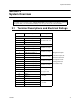
Installation 4.3 Current Requirements (Standby and Alarm) 4.3.1 Current Drawn From Host Panel Table 4-1 shows the 5495 current draw requirements from the main control panel when the panel’s notification appliance circuit is in alarm. The current draw from the main panel when it is supervising the 5495 is the same current draw that would be present when the main panel supervises an ordinary notification appliance circuit.
Model 5495 Distributed Power Module Installation Manual Table 4-2: Battery Calculation Worksheet Number of Devices Device X For each device use this formula: This column 5495 Distributed Power Module (Current draw from battery) Standby Current Current per Device This column Standby: 1 = Current per number of devices.
Installation 4.4 Connecting the 5495 to a Control Panel Figure 4-2 shows the general layout of the 5495 PC board. This section also provides specific wiring details for accessories. Figure 4-2 The Model 5495 PC Board Layout Consult the installation manual for specific wiring information for the control panel being used.
Model 5495 Distributed Power Module Installation Manual 4.4.1 Common Trouble Relay The 5495 has a Form C trouble relay built into Terminals 11-13. The relay provides a normally open and a normally closed contact, both of which are rated at 2.5A. The trouble relay will deactivate under any trouble condition. A typical application of the trouble relay is to connect the 5495 normally closed (N.C.) contacts in series with the EOL supplied with the fire alarm control panel.
Installation 4.5 Notification Appliance Wiring Note: Not all devices can use the sync feature. Be sure to check Appendix A to ensure the device you have chosen will work with this feature. Important! For all synchronization options, input 1 is the strobe input and input 2 is the audible input. The signals to input 1 and input 2 must be DC signals for the synchronization patterns to work properly. When it is desired to activate both strobes and audibles, input 1 and input 2 must be active.
Model 5495 Distributed Power Module Installation Manual pass the added current load from notification appliances. Figure 4-4 Class A Supervised Input/Output Connections 4.5.2 Class B Supervised Wiring Figure 4-5 shows how to wire for Class B input and output supervision. Use in/out wiring methods for proper supervision (Refer to the Appendix for notification appliances approved for use with the 5495.) Class B Output Notification Circuits Figure 4-5 shows four, 1.5 A devices wired as Class B. Place a 4.
Installation Class B Supervised Input Circuits Figure 4-5 shows Class B supervised wiring from a fire alarm control panel to the 5495. Use an EOL resistor as shown to enable notification appliance circuit input supervision. Some panels use EOLs that have a different value from the 4.7k ohm EOL resistor used by the 5495. In this case, the EOL must be UL listed for the fire alarm control panel (not the 5495). Figure 4-5 Class B Supervised Input/Output Connections 4.
Model 5495 Distributed Power Module Installation Manual 4.7 Battery Connection Use two 12 VDC, 7 AH gel cell batteries inside the 5495 cabinet. For batteries larger than 7 AH (not to exceed 35 AH) use the RBB Remote Battery Box. It is recommended that you replace the batteries every five years. The following steps and diagram explain how to connect the batteries. 1. Connect the black wire to the negative (-) side of Battery #1. 2.
Installation 4.8 DIP Switch Settings A 7-position DIP switch on the 5495 board allows you to select the following: • • • • • How long the 5495 will wait before indicating a loss of AC. Which input (Input 1 or Input 2) will control the NACs. Which NACs to wire as Class A and Class B. Auxiliary power state. Which NACs to operate as steady, ANSI temporal, or sync. outputs Refer to Figure 4-2 for the location of the DIP switch on the 5495 board.
Model 5495 Distributed Power Module Installation Manual 4.8.1 Selecting the Standard Input/Output Configurations Figure 4-7 and Figure 4-8 show the position of each switch for the non-synchronized input and output configurations. The position of Switches 4 and 5 does not affect the relationship of inputs to outputs. Note: The 5495 checks switches 1, 2, 3, and 6 only when powering up the 5495.
Installation 4.8.1.1 Input/Output Configurations That Select ANSI Temporal-Coded Outputs The DIP switch settings marked with an asterisk (*) in Figure 4-7 and Figure 4-8 are designed to produce ANSI temporal-coded outputs from a constant input. The figures shown below compare the output patterns of configurations before and after the addition of this feature.
Model 5495 Distributed Power Module Installation Manual 4.8.2 Selecting Synchronized Output Configurations The following sections describe how to configure the 5495 as a synchronization power expander for Amseco, Faraday, Gentex, System Sensor, or Wheelock synchronized horn/strobe appliances. Note: In order for the synchronization feature to operate properly, make sure you have set the DIP switches for the proper manufacturer. See Sections 4.8.2.1, 4.8.2.2, or 4.8.2.3.
Installation 4.8.2.3 Selecting Synchronized System Sensor Configurations To select the input/outputs for System Sensor synchronized appliances, set the DIP switches as shown in Figure 4-11. Figure 4-11 System Sensor Synchronized Configurations 4.8.2.4 Selecting Synchronized Wheelock Configurations To select the input/outputs for Wheelock synchronized appliances, set the DIP switches as shown in Figure 4-12. Figure 4-12 Wheelock Synchronized Configurations 4.8.2.
Model 5495 Distributed Power Module Installation Manual 4.8.3 Setting the Loss of AC Delay Normal selection for reporting loss of AC is 3 hours. The ON position is for test purposes only and the normal position for Switch 4 is OFF. For testing the Low AC reporting, you can temporarily turn Switch 4 ON without removing power. Note: Remember to turn the switch OFF when testing is complete. Figure 4-14 Setting DIP Switch 4 4.8.
Sample Applications Section 5 Sample Applications The drawings in this section show various 5495 configurations, including “daisy-chaining”. 5.
Model 5495 Distributed Power Module Installation Manual Note: When multiple power supplies are used with one control unit they will not sync with each other 5495 Local Fire Alarm Control Panel 5495 Figure 5-3 One Control Activating Two 5495s 5495 Local Fire Alarm Control Panel 5495 5495 Figure 5-4 One Control Activating Three 5495s in Series 24 151161
Sample Applications 5495 Local Fire Alarm Control Panel 5495 5495 Figure 5-5 Each Control NAC Activates Five Output NACs 5.2 Non-Resettable Power Application The 5495 provides a dedicated 3 A auxiliary power output that you can select as non-resettable (output is always on). See Section 4.8.4 for setting the auxiliary power. If you need more than 3 A, wire the inputs as shown in Figure 5-6.
Model 5495 Distributed Power Module Installation Manual 5.3 Door Holder Application In a typical door holder application, the door holder power must be interrupted to close all fire doors under the following conditions: • • Any active alarm condition. AC power failure (to conserve battery power). To close the fire doors in these situations, wire an N.C. programmable relay from the FACP in series with the auxiliary power to the door holders as shown in Figure 5-7.
Troubleshooting Section 6 Troubleshooting Light-emitting diodes (LEDs) indicate fault conditions. This section describes the LED states. 6.1 LEDs The eight LEDs indicate a fault in one of the circuits (either NACs 1 through 4, auxiliary power, earth fault, low AC, or battery). A fault in the LED's corresponding circuit will light the LED (labeled on the board). Their functions are as follows: LED Color Description OUT1 Yellow When ON, output circuit 1 is in trouble or in an overcurrent state.
Model 5495 Distributed Power Module Installation Manual 6.2 Trouble Conditions Trouble Condition Low AC What Happens Input 1 and Input 2 supervision circuits open after a 6 hour delay. (AC input voltage is low or off The green AC LED turns off as soon as low AC or loss of AC occurs (does not wait 6 for 6 hours or longer.) hours). The trouble relay is de-energized after a 6 hour delay. The trouble restores within 1 minute of the AC voltage restoring to a normal level.
Troubleshooting 6.3 Earth Fault Resistance Table 6-1 lists the earth fault resistance detection for each applicable terminal on the FACP.
Model 5495 Distributed Power Module Installation Manual 6.4 Removing and Replacing the Control Panel This section provides instruction on how to remove and replace the control panel if it is determined that the control panel needs to be repaired or replaced. 6.4.1 Removing the Control Panel Follow these step to properly remove the control panel: 1. Remove the two heat sink screws. The heat sink screws are located on the top of the cabinet. See Figure 6-1. Figure 6-1 Mounting Screw Locations 2.
Appendix A UL Listed Notification Appliances For proper operation, you must use polarized devices with a Model 7628 4.7k ohm EOL resistor on each circuit. All supervised notification appliances used with the 5495 must be polarized. Note: Not all devices can use the Sync feature, be sure to check Table A-1 to ensure the device you have chosen will work with this feature. Synchronization is UL listed for multi-circuit operation. A.
Model 5495 Distributed Power Module Installation Manual Table A-1: Compatible Notification Appliances Manufacturer Model Type Vibrating Bell 476 Vibrating Bell 477 Single Stroke Bell 2700 -M.
UL Listed Notification Appliances Table A-1: Compatible Notification Appliances Manufacturer Faraday (cont.
Model 5495 Distributed Power Module Installation Manual Table A-1: Compatible Notification Appliances Manufacturer FCI 34 Model Audio Visual Type S2415-FC Strobe S241575-FC Strobe S2430-FC Strobe 130-3117C Mini Horn 130-3147C Mini Horn BLV-6 Vibrating Bell BLV-10 Vibrating Bell BLVCH Vibrating Chime H12/24-FC Horn H12/24W-FC Horn H12/24K-FC Horn HC12/24-FC Horn HC12/24W-FC Horn HC12/24K-FC Horn P2415-FC Horn/Strobe P2415W-FC Horn/Strobe P2415K-FC Horn/Strobe P241575
UL Listed Notification Appliances Table A-1: Compatible Notification Appliances Manufacturer FCI Federal Signal 151161 Model Audio Visual Type P2430W-FC Horn/Strobe P2430K-FC Horn/Strobe P2475-FC Horn/Strobe P2475W-FC Horn/Strobe P2475K-FC Horn/Strobe P24110-FC Horn/Strobe P24110W-FC Horn/Strobe P24110K-FC Horn/Strobe S2430W-FC Strobe S2430K-FC Strobe S2475-FC Strobe S2475W-FC Strobe S2475K-FC Strobe S24110-FC Strobe S24110W-FC Strobe S24110K-FC Strobe 450 Horn VAL
Model 5495 Distributed Power Module Installation Manual Table A-1: Compatible Notification Appliances Manufacturer Model GEC-24-15 GEC-24-30 GEC-24-60 GEC-24-75 GEC-24-177 GEC-24-110 GEC-24-15/75 GX91 GX93 Audio Visual x x x x Horn/Strobe x x x x x x x x x x x x Horn/Strobe Horn/Strobe Horn/Strobe Horn/Strobe Horn/Strobe MiniHorn Temporal Tone Horn x x x x x x x Horn/Strobe GCC24 x x x x x x x GCCR24 x x Multi Candella Horn/Strobe Ceiling Mount x x x x x x x x x Multi Candella Strobe Ce
UL Listed Notification Appliances Table A-1: Compatible Notification Appliances Manufacturer Model Audio Strobe GES3-24 GESR-24 x Multi Candella Strobe GEH-24 x ST24-30 ST24-60 ST24-75 ST24-110 ST24-1575 WGEC24-75W WGES24-75W WGMS-24-X 151161 Type x x GES24-177 Gentex (cont.
Model 5495 Distributed Power Module Installation Manual Table A-1: Compatible Notification Appliances Manufacturer Model CHR CHW CHSR CHSW HR Audio x x x x x PC2R PC2R-P P2RH P2RH-P PC2RH PC2RH-P System Sensor P2W P2W-P PC2W PC2W-P P2WH P2WH-P PC2WH PC2WH-P P2RK PC2RK P2RHK PC2RHK P4R PC4R P4RH P4W 38 Chime Chime 2-Wire Chime/Strobe x x x x x x x x x x x x x x x x x x x x x x x x x x x x x x x x x x x x x x x x x x 2-Wire Horn/Strobe x x x x 4-Wire Horn/Strobe High Candela HRK P2R-P Type
UL Listed Notification Appliances Table A-1: Compatible Notification Appliances Manufacturer Model PC4W P4WH PC4WH P4RK PC4RK P4RHK PC4RHK PC4RH Audio Visual x x x x 4-Wire Horn/Strobe x x x x x x x x x x x x x 4-Wire Horn/Strobe High Candela x x x x x x x x x x x x x x x x x x x x Strobe x 2-Wire Low Frequency Sounder Strobe SR SR-P SCR SCR-P SRH SRH-P SCRH System Sensor (cont.
Model 5495 Distributed Power Module Installation Manual Table A-1: Compatible Notification Appliances Manufacturer Model AH-12 AH-24 AH-12WP AH-24WP AMT-241575W Audio AMT-12/24 AMT-12/24 NYC Horn x x x Horn Weatherproof x x x AS-121575W NH-12/24 AS-241575W AS-24MCC Wheelock AS-24MCCH AS-24MCW AS-24MCWH ASWP-2475W ASWP-2475C ASWP-24MCWH ASWP-24MCCH CH-70 CH-90 CH70-241575W CH70-24MCW CH70-24MCWH CH90-24MCC 40 Type x x AMT-24MCW AMT-241575W-NYC Visual x x x x x x x x x x x x Horn Horn Weath
UL Listed Notification Appliances Table A-1: Compatible Notification Appliances Manufacturer Model Audio x CH90-24MCCH HS-24 x HS4-241575W x x x x x HS4-24MCW HS4-24MCWH HS4-24MCC MIZ-24S MT-121575W MT-241575W x MT-24MCW MTWP-2475W MTWP-2475C MTG-121575W MTR-121575W Wheelock (cont.
Model 5495 Distributed Power Module Installation Manual Table A-1: Compatible Notification Appliances Manufacturer Model RSS-121575W RSS-241575W RSS-24MCC RSS-24MCCR RSS-24MCCH RSS-24MCCHR RSS-24MCW RSS-24MCWH RSSP-121575W RSSP-241575W RSSR-2415W RSSR-2415C RSSR-2475W RSSR-2475C Wheelock (cont.
UL Listed Notification Appliances Table A-1: Compatible Notification Appliances Manufacturer Model Audio RSSWP-24MCWH ZRS-MCWH ZRS-24MCC ZRS-24MCCH Wheelock (cont.
Model 5495 Distributed Power Module Installation Manual 44 151161
Silent Knight Fire Product Warranty and Return Policy General Terms and Conditions • • All new fire products manufactured by Silent Knight have a limited warranty period of 36 months from the date of manufacture against defects in materials and workmanship. See limited warranty statement for details. This limited warranty does not apply to those products that are damaged due to misuse, abuse, negligence, exposure to adverse environmental conditions, or have been modified in any manner whatsoever.
12 Clintonville Road Northford, CT 06472 USA RA Number:___________________ Manufacturer Warranties and Limitation of Liability Manufacturer Warranties.
Silent Knight 12 Clintonville Road Northford, CT 06472-1610 203-484-7161 Fax: 203-484-7118 www.silentknight.