USB to RS-422/485 Serial Adapter Quick Installation Guide Introduction The USB to RS-422/485 Serial Adapter provides additional RS-422/485 serial port(s) to your systems. Key Features and Benefits • • • • • Compliant with Universal Serial Bus 2.
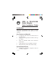
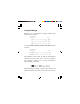
• Windows® 8 (32-/64-bit) / Windows 7 (32/64-bit) / Vista (32-/64-bit) / XP (32-/64bit) / Server 2003 & 2008 (32-/64-bit) / Server 2008 R2 Package Contents • • • • USB to RS-422/485 Serial Adapter USB cable (Type A/B) Termination resistor jumpers (2 for IDSC0P11-S1, 4 for ID-SC0Q11-S1, 8 for IDSC0R11-S1) Software CD & quick installation guide Layout 1-Port USB to RS-422/485 Serial Adapter Status LED USB Type B Serial output Figure 1: ID-SC0P11-S1 Layout 2 DIP switch
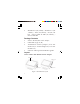
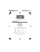
2-Port USB to RS-422/485 Serial Adapter Status LED USB Type B DIP switch (P1) Serial output DIP switch (P2) Figure 2: ID-SC0Q11-S1 Layout 4-Port USB to RS-422/485 Serial Adapter Serial output Status LED 5V power jack DIP switch (P1-P4) USB Type B (optional) Figure 3: ID-SC0R11-S1 Layout Status LED • • Tx: Flashing green when sending data Rx: Flashing yellow when receiving data 3
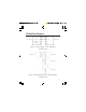
• 5V power jack (optional): Connect your power adapter here (not included). Note: Most serial devices do not require additional power through the serial port. Refer to your serial device's manual for more information. DIP Switch Auto RS-422/485 (1-ON, 2-OFF) This is default setting. The COM port will automatically detect device status and control the data transmitting or receiving. See Figure 4a. RS-422 or 4-Wire RS-485 (1-OFF, 2-ON) Full duplex mode. See Figure 4b.
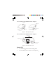
Termination Resistor Open the cover of the USB to RS-422/485 Serial Adapter to configure the jumper settings. 1. Unscrew the screw(s) at the bottom of the Adapter. Bottom screw Figure 5 2. Slide the bottom cover in the direction of the serial output to open. Serial output Figure 6 3. Follow the instructions on page 6 to configure the jumper settings.
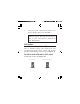
Jumper Settings RS-422 or 4-wire RS-485 working model with termination resistor. USB to RS-422/485 Serial Adapter Device 2-wire RS-485 working model with termination resistor. USB to RS-422/485 Serial Adapter Device The adapter comes with Tx and Rx termination resistors for each serial port. You can configure the jumper settings to avoid impedance mismatched problems. Default jumper setting is Open (disconnect 120 ohms termination resistor across the two wires).
P1- Tx P1- Rx Figure 7: Tx and Rx jumper for each port Pin Assignment 1 5 6 9 Note: Pins 6 to 9 have no function.
RS-422 Wire Diagram USB to RS-422 Pin 1: TxD- RxD- Pin 2: TxD+ RxD+ Pin 3: RxD- TxD- Pin 4: RxD+ TxD+ RS-422 device Figure 9: point-to-point / 4-wire full-duplex communication USB to RS-422 RS-422 device RS-422 device RS-422 device Figure 10: point-to-multi point / 4-wire full-duplex communication 8
RS-485 Wire Diagram USB to RS-485 Pin 1: TxD- D- Pin 2: TxD+ D+ RS-485 device Pin 3: RxDPin 4: RxD+ Figure 11: Point-to-point / 2-wire half-duplex communication USB to RS-485 RS-485 device RS-485 device RS-485 device Figure 12: Point-to-multi point / 2-wire half-duplex communication 9
Windows Installation Follow the instructions below to install the USB to RS-422/485 Serial Adapter drivers. Note: Do not plug the Adapter to your computer until instructed to do so. Windows 8 (32-/64-bit) / Windows 7 (32-/ 64-bit) / Server 2008 R2 1. 2. 3. 4. 5. 6. 10 Insert the driver CD. Close the CD autoplay box if prompted. Press Windows key and R, type D:\setup.exe, and click OK. (Change D: to match your CD/DVD-ROM drive letter) At the User Account Control, click Yes. For 2008 R2, skip this step.
Windows Vista (32-/64-bit) 1. 2. 3. 4. 5. Insert the driver CD. Close the CD autoplay window. Click Start, at the Start Search, type D:\setup.exe, click OK. (Change D: to match your CD/DVD-ROM drive letter) At the User Account Control, click Allow. Repeat steps 2 & 3. Plug the adapter into the computer, click Cancel at the Found New Hardware (if prompted). The driver will install automatically. Windows XP (32-/64-bit) / Server 2003 (32-/ 64-bit) / Server 2008 (32-/64-bit) 1. 2. 3. 4.
5. Plug the adapter into the computer, click Cancel at the Found New Hardware (if prompted). To Verify Windows Installation 1. 2. 12 Go to Device Manager to verify installation. For Windows 8 / 7 / XP / Server 2003: Right click Computer or My Computer, click Manage, then click Device Manager. For Windows Vista: Right click Computer, click Manage, click Continue, then click Device Manager.
Blank Page 13
Blank Page 14
Technical Support and Warranty QUESTIONS? SIIG’ s Online Support has answers! Simply visit our web site at www.siig.com and click Support. Our online support database is updated daily with new drivers and solutions. Answers to your questions could be just a few clicks away. You can also submit questions online and a technical support analyst will promptly respond. SIIG offers a 3-year manufacturer warranty with this product.
About SIIG, Inc. Founded in 1985, SIIG, Inc. is a leading manufacturer of IT connectivity solutions (including Serial ATA and Ultra ATA Controllers, FireWire, USB, and legacy I/O adapters) that bridge the connection between Desktop/ Notebook systems and external peripherals. SIIG continues to grow by adding A/V and Digital Signage connectivity solutions to our extensive portfolio.