Serial ATA 4-Channel RAID Quick Installation Guide Introducing the Serial ATA 4-Channel RAID The Serial ATA 4-Channel RAID is an ultra high-speed four channel Serial ATA controller for use in Pentium class computers. It achieves burst data transfer rates up to 150MB/s (1.5Gb/s) and supports various brands of hard disk drives with capacities greater that 137GB. Features and Benefits • • • • • • • Compliant with Serial ATA Specification, revision 1.0 Compliant with PCI Specification, revision 2.
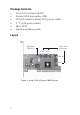
Package Contents • • • • • • Serial ATA 4-Channel RAID 4 Serial ATA data cables (1M) 2 Dual Connector Serial ATA power cables 2 "Y" split power cables Driver CD Quick installaton guide Layout Hard Disk LED Pins Serial ATA Connectors CN4 CN3 CN2 CN1 Figure 1.
Hardware Installation General instructions for installing the card are provided below. Since the design of computer cases and motherboards vary, refer to your computer’s reference manual for further information, if needed. Static electricity discharge may permanently damage your system. Discharge any static electricity build up in your body by touching your computer case for a few seconds. Avoid any contact with internal parts and handle cards only by their external edges. 1. 2. 3. 4. 5. 6. 7.
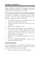
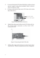
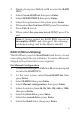
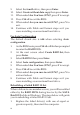
2. 3. Connect the Serial ATA hard disk drive to the system power supply using the included Dual Connector Serial ATA power cable. Connect one end of the Serial ATA data cable to the hard disk drive. Serial ATA cable Power cable adapter Figure 2. Hard disk drive connections 4. Attach the other end of the Serial ATA data cable to the Serial ATA connector on the Serial ATA 4-channel RAID. Figure 3. Connecting the Serial ATA cable 5. 4 Follow the same instructions to connect up to four hard drives.
Note: If it is your desire to monitor disk activity of the Serial ATA hard drives, you may at this time connect the hard disk LED of the system case to the Hard Disk LED Pins on the Serial ATA controller, see Board Layout on page 2 for the location of the pins. All four Serial ATA Connectors activate the LED. For most systems connect the Red wire to the pin farthest from the mounting bracket. 6. Replace the computer cover and reconnect the power cord. Go to RAID Arrays to configure the RAID BIOS.
8. 9. 10. 11. 12. 13. Select the second drive, press Enter. If applicable select the 3rd and 4th drives pressing enter after each selection. After selecting the last drive, you are asked Are You Sure (Y/N)?, press Y to accept. Press Ctrl+E to exit the BIOS. When asked Are you sure to exit (Y/N)?, press Y to exit. Continue with Fdisk and Format steps as if you were installing a conventional hard drive. For Auto Configuration The default chunk size is 64k when selecting Auto configuration. 1. 2. 3. 4. 5. 6.
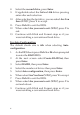
RAID 1 (Mirror) For New/Blank Hard Drives 1. As the BIOS boots press Ctrl+S or F4 when prompted to enter the RAID BIOS. 2. At the next screen select Create RAID Set, then press Enter. 3. At the next screen select RAID1 then press Enter. 4. Select Auto configuration, then press Enter. 5. When asked Are You Sure (Y/N)?, press Y to accept. 6. Press Ctrl+E to exit the BIOS. 7. When asked Are you sure to exit (Y/N)?, press Y to exit and reboot. 8.
9. 10. 11. When asked Are You Sure (Y/N)?, press Y. Press Ctrl+E to exit the BIOS. When asked Are you sure to exit (Y/N)?, press Y to exit. Note: If during restart the RAID BIOS reports an incomplete Mirror set, disregard the message, continue booting, and let the Mirror rebuild. Creating a SPARE Drive When a hard drive failure occurs in a mirror set, the autorebuild feature enables a drive designated as SPARE to become the new member of the mirror set. 1.
2. 3. 4. 5. 6. 7. 8. During boot press Ctrl+S or F4 to enter the RAID BIOS. Select Create RAID set then press Enter. Select SPARE DRIVE then press Enter. Select the replacement drive then press Enter. When asked Are You Sure (Y/N)?, press Y to confirm. Press Ctrl+E to exit. When asked Are you sure to exit (Y/N)?, press Y to exit. Note: If during restart the RAID BIOS reports an incomplete RAID set, disregard the message, continue booting, and let the Mirror rebuild.
9. 10. 11. 12. 13. 14. Select the fourth drive, then press Enter. Select Create without data copy then press Enter. When asked Are You Sure (Y/N)?, press Y to accept. Press Ctrl+E to exit the BIOS. When asked Are you sure to exit (Y/N)?, press Y to exit. Continue with Fdisk and Format steps as if you were installing a conventional hard drive. For Auto Configuration The default chunk size is 64k when selecting Auto configuration. 1. 2. 3. 4. 5. 6. 7. 8.
2. 3. 4. 5. 6. 7. 8. During boot press Ctrl+S or F4 to enter the RAID BIOS. Select Create RAID set then press Enter. Select SPARE DRIVE then press Enter. Select the replacement drive then press Enter. When asked Are You Sure (Y/N)?, press Y to confirm. Press Ctrl+E to exit. When asked Are you sure to exit (Y/N)?, press Y to exit. Note: If during restart the RAID BIOS reports an incomplete RAID set, disregard the message, continue booting, and let the Mirror rebuild.
8. When asked Are you sure to exit (Y/N)?, press Y to exit and reboot. Note: The hard disk will show up as Contiguous in the SATARAID5 GUI. JBOD Drive Setup This RAID Array combines the full capacity of two or more hard drives to form one logical drive. Since this configuration will destroy all existing data on each hard drive, use blank or new hard drives or back up the existing data before connecting to the raid controller. 1. 2. 3. 4. 5. 6.
RAID5 While RAID5 feature is enabled in the SATA Raid 5 BIOS, this RAID Array is not supported by the Serial ATA 4-Channel RAID controller. Please use it at your own risk. Deleting RAID Arrays 1. 2. 3. 4. 5. As the BIOS boots press Ctrl+S or F4 when prompted to enter the RAID BIOS. Select Delete RAID Set, then press Enter. Select the RAID set then press Enter. When asked Are You Sure (Y/N)?, press Y to confirm. The RAID set is now deleted.
Low Level Format Low Level Format is built into the RAID BIOS to make it more convenient to erase the entire contents of a hard disk drive, including data, drive and partition information. The Low Level Format utility works on single hard drives only, before the RAID set is configured. Software Installation This section provides information on how to install the Serial ATA 4-channel RAID drivers. Windows 7 (32-bit) For A New Windows 7 (32-bit) Installation 1.
2. 3. 4. 5. 6. 7. At the desktop, insert the driver CD. Close the AutoPlay box if prompted. Right click Computer, click Manage, click Device Manager. Under Other devices, right click RAID Controller, click Update Driver Software. Click Browse my computer for driver software. Type D:\32bit, click Next. (Change D: to match your CD/DVD-ROM drive letter) At Windows has successfully updated your driver software, click Close to complete the installation.
For An Existing Windows 7 (64-bit) Installation 1. 2. 3. 4. 5. 6. 7. Setup your RAID array, and boot up Windows. At the desktop, insert the driver CD. Close the AutoPlay box if prompted. Right click Computer, click Manage, click Device Manager. Under Other devices, right click RAID Controller, click Update Driver Software. Click Browse my computer for driver software. Type D:\64bit, click Next.
5. 6. 7. Double click your CD-ROM drive. For 32-bit Windows Vista: Click OK. For 64-bit Windows Vista: Select 64bit, then click OK. Select Silicon Image SiI ..., then click Next. Follow the on-screen instructions to complete Windows Vista operating system installation. When Windows installation completes, go to SATARaid5 GUI on page 24 and install the RAID monitoring utility. For An Existing Windows Vista Installation 1. 2. 3. 4. 5. Install the board and boot up Windows.
2. 3. Follow Microsoft installation procedure to install Windows accordingly. At the Windows Setup screen, press F6 to install the driver. Note: Prior to this step, you may be prompted to restart in order to continue with the installation. 4. 5. 6. Insert the driver diskette that you made earlier. Press S then press Enter. Select Silicon Image SiI 3114 SoftRaid 5 Controller for Windows XP/Server 2003, press Enter. Press Enter to continue and follow on-screen instructions to complete the installation.
Windows XP (64-bit) / Server 2003 (64-bit) For A New XP (64-bit) / Server 2003 (64-bit) Installation A new installation requires a floppy disk for the driver installation. To make this floppy disk, copy the contents of the 64bit folder, found on the driver CD, onto a blank floppy disk then follow the directions below. 1. 2. 3. 4. 5. 6. Setup the RAID array prior to Windows installation. Follow Microsoft procedure to install Windows accordingly. At the Windows Setup screen, press F6 to continue.
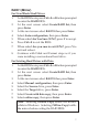
To Verify XP / Server 2003 / 2000 Installation 1. 2. Right click My Computer, click Manage, click Device Manager. Double click SCSI and RAID controllers, and Silicon Image SiI 3114 SoftRaid 5 Controller should be displayed. Windows Server 2008 (32-bit) For A New Server 2008 (32-bit) Installation These instructions follow bootable Windows Installation CD/DVD-ROM procedure. Your steps may differ when using a different media for Windows installation. 1. 2. 3. 4. 5. 6. 7. 8.
4. 5. Click Next, then click Close. Shutdown Windows, and setup your RAID array. When Windows resumes, go to SATARaid5 GUI on page 24 and install the RAID monitoring utility. Windows Server 2008 (64-bit) For A New Server 2008 (64-bit) Installation These instructions follow bootable Windows Installation CD/DVD-ROM procedure. Your steps may differ when using a different media for Windows installation. 1. 2. 3. 4. 5. 6. 7. 8. Setup the RAID array prior to Windows installation.
5. Remove the driver CD, shutdown Windows, and setup your RAID array. When Windows resumes, go to SATARaid5 GUI on page 24 and install the RAID monitoring utility. To Verify Windows Server 2008 Installation 1. 2. 3. Right click Computer, click Manage. Double click Diagnostics, select Device Manager. Double click Storage controllers, and Silicon Image SiI 3114 SoftRaid5 Controller should be displayed.
4. 5. 6. 7. When prompted press S to specify the location of the driver. Insert the driver diskette you made earlier, then press Enter. Select Silicon Image Sil 3114 SoftRaid 5 Controller for Windows 2000, then press Enter. Press Enter to finish driver installation, then follow the on-screen instructions to complete the Windows installation. When Windows installation completes, go to SATARaid5 GUI on page 24 and install the RAID monitoring utility. For An Existing Windows 2000 Installation 1.
SATARaid5 GUI The SATARaid5 GUI provides the user an easy way to monitor your RAID set. SATARaid5 GUI Installation 1. 2. 24 At the Windows desktop, insert the driver CD. For Windows 7 / Vista / Server 2008 For 32-bit: Click Start, in Start Search box, type D:\32bitgui.msi, then press Enter. (Change D: to match your CD/DVD-ROM drive letter) For 64-bit: In Start Search box, type D:\64bitgui.msi, then press Enter.
SATARaid5 GUI Overview The SATARaid5 GUI will automatically start when Windows boots up. If the GUI does not automatically start or is closed by the user, choose the SATARaid5 program from the start menu to launch the program. Upon launching the GUI, the main window should appear similar to what is displayed below and on the next few pages. RAID Groups window Device Configuration window RAID Groups window This window identifies SATA host adapters and configured RAID groups.
Device Configuration window This window identifies all physical drives and their partitions. A physical drive can be partitioned into several portions and each portion can be a RAID group member. SATARAID 5 Configuration Menu SATARAID5 configuration menu includes customization of the settings for Log File, Popup and Advanced Options. By clicking on File, then Configuration, the user may customize the settings for Log File, Popup and Advanced Options tabs.
Log File The log file is used to store event information received from all the RAID drivers. The log file can be viewed with any text viewer (such as Notepad) or with the Event Log window of SATARAID5 GUI. Use the Log File tab to enable/disable the log file, set where the log file should be stored and the name of the file as well. Popup The popup window is a visual notification that an event has occurred. The popup window can be disabled or set to popup for only certain event levels.
Legacy (Bootable) Support: When this feature is selected, Legacy Support menu will be available in the menu bar. The Legacy Support menu includes a list of menu items to support RAID functions for legacy RAID groups. Delete Member Support: When this feature is selected, Delete Member menu item will be available under the Device menu. The Delete Member menu item allows the user to delete a member from RAID 1 group.
Delete Orphan An orphan device segment is part of a RAID group that cannot access another device segment within the same RAID group. When a member of a RAID group fails (such as a loss of power or a complete hard disk failure), it becomes an orphan. This command displays the Delete Orphan Segment window to show all orphan segments and allows the user to delete selected orphan segments. Make Pass-Thru Removes any Metadata on the drive so it will function as an ordinary hard disk drive.
Rebuild Priority: Select from the available list. RAID 0 and virtual disk do not require this. 10 is the highest level of rebuild priority which means that rebuild times will be faster but will take more CPU resources to rebuild. Devices: Select RAID member devices from the available device segment list. Rebuild RAID Group This command displays a dialog box to let the user choose a replacement segment to rebuild a non-fault tolerant RAID group. Delete RAID Group Lets the user choose RAID group(s) to delete.
Window Menu Command Task Manager This command displays the Task Manager window. The Task Manager window list all RAID and disk management tasks that have been started and/or done. This window provides the user with the ability to schedule any RAID and disk management operations including RAID group creation, rebuild and test. The Task Manager window has it's own menu bar. All options available via the menu bar are shown below. Open, Save and Print: These options will be available in future revisions.
Sorting: This command displays a dialog box to the the user choose up to 3 items to sort event items in the event log. Fields: This command displays a dialog box to let the user choose which fields will be shown in the event log. Resources This command displays the Resources Information window. This feature is for debugging purpose only. Legacy Support Menu Command Create Legacy RAID Group This command displays a dialog box to let the user create legacy (bootable) RAID groups.
Delete Legacy RAID Group This command displays a dialog box to let the user choose legacy RAID groups to delete. This item is disabled if no legacy RAID group exists. Convert Legacy RAID Group This command displays a dialog box to let the user choose legacy RAID groups to convert to new RAID groups of the same RAID type. This item is disabled if no legacy RAID group exists. Create/Delete/Convert Legacy Spare These commands display a dialog box to let the user configure a legacy spare.
Blank Page 34
Technical Support and Warranty QUESTIONS? SIIG’s Online Support has answers! Simply visit our web site at www.siig.com and click Support. Our online support database is updated daily with new drivers and solutions. Answers to your questions could be just a few clicks away. You can also submit questions online and a technical support analysts will promptly respond. SIIG offers a lifetime manufacturer warranty with this product. Please see our web site for more warranty details.
About SIIG, Inc. Founded in 1985, SIIG, Inc. is a leading manufacturer of IT connectivity solutions (including Serial ATA and Ultra ATA Controllers, FireWire, USB, and legacy I/O adapters) that bridge the connection between Desktop/ Notebook systems and external peripherals. SIIG continues to grow by adding A/V and Digital Signage connectivity solutions to our extensive portfolio.