Serial ATA 4-Channel RAID Quick Installation Guide Introducing the Serial ATA 4-Channel RAID The Serial ATA 4-Channel RAID is an ultra high-speed four channel Serial ATA controller board for use in Pentium-class computers. It achieves burst data transfer rates up to 150MB/s (1.5Gb/s) and supports various brands of hard disk drives with capacities greater that 137GB. Features and Benefits • • • • • • • • Compliant with Serial ATA Specification, revision 1.0 Compliant with PCI Specification, revision 2.
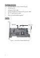
Package Contents • • • • • • (1) Serial ATA 4-Channel RAID board (1) Driver CD (4) Serial ATA cable (2) Dual Connector Serial ATA power cable (2) "Y" split power cable This quick installaton guide Layout Hard Disk LED Pins Serial ATA Connectors CN4 CN3 CN2 CN1 Figure 1.
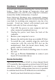
Hardware Installation General instructions for installing the card are provided below. Since the design of computer cases and motherboards vary, refer to your computer’s reference manual for further information, if needed. Static Electricity Discharge may permanently damage your system. Discharge any static electricity build up in your body by touching your computer’s case for a few seconds. Avoid any contact with internal parts and handle cards only by their external edges. 1. 2. 3. 4. 5. 6. 7.
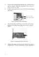
2. 3. Connect the Serial ATA hard disk drive to the system power supply using the included Dual Connector Serial ATA power cable. Connect one end of the Serial ATA cable to the hard disk drive. Serial ATA cable Power cable adapter Figure 2. Hard disk drive connections 4. Attach the other end of the Serial ATA cable to the Serial ATA connector on the Serial ATA 4-channel RAID. Figure 3. Connecting the Serial ATA cable 5. 4 Follow the same instructions to connect up to four hard drives.
Note: If it is your desire to monitor disk activity of the Serial ATA hard drives, you may at this time connect the hard disk LED of the system case to the Hard Disk LED Pins on the Serial ATA controller, see Board Layout on page 2 for the location of the pins. All four Serial ATA Connectors activate the LED. For most systems connect the Red wire to the pin farthest from the mounting bracket. 6. Replace the computer cover and reconnect the power cord. Go to RAID Arrays to configure the RAID BIOS.
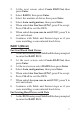
RAID 0 (Striping) This RAID array to be used on New/Blank hard drives. Striping will destroy existing data on the hard drive. For Manual Configuration 1. As the BIOS boots press Ctrl+S or F4 when prompted to enter the RAID BIOS. 2. At the next screen select Create RAID Set, then press Enter. 3. Select RAID0, then press Enter. 4. Select the number of drives then press Enter. 5. Select Manual configuration then press Enter. 6. Select chunk size from 4k, 8k, 16k, 32k, 64k or 128k, then press Enter. 7.
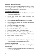
2. 3. 4. 5. 6. 7. 8. 9. At the next screen select Create RAID Set, then press Enter. Select RAID0, then press Enter. Select the number of drives then press Enter. Select Auto configuration, then press Enter. When asked Are You Sure (Y/N)?, press Y to accept. Press Ctrl+E to exit the BIOS. When asked Are you sure to exit (Y/N)?, press Y to exit and reboot. Continue with Fdisk and Format steps as if you were installing a conventional hard drive. RAID 1 (Mirror) For New/Blank Hard Drives 1.
2. 3. 4. 5. 6. 7. 8. At the next screen select Create RAID Set, then press Enter. At the next screen select RAID1 then press Enter. Select Manual configuration, then press Enter. Select the Source drive, press Enter. Select the Target drive, press Enter. Select Create with data copy, then press Enter. Select online copy, then press Enter. Note: Selecting Online Copy builds the mirror while in Windows. Selecting Offline Copy builds the mirror before exiting the RAID bios. 9.
6. 7. Press Ctrl+E to exit. When asked Are you sure to exit (Y/N)?, press Y to exit. The SPARE drive will not be seen by Windows, however, it remains in the background waiting to rebuild the mirror in the event of a hard drive failure. Rebuilding a Failed Mirror Set When a failure to one member occurs, you will be notified either by the RAID BIOS during boot or by the SATA Raid GUI while in Windows. The steps below will guide you in rebuilding a failed mirror set. 1. 2. 3. 4. 5. 6. 7. 8.
RAID 0+1 (Mirror+Striping) This RAID set is used on New/Blank hard drives, do not use existing hard drive(s) with data. To create a MirroredStriped set four hard drives are required. For Manual Configuration 1. As the BIOS boots press Ctrl+S or F4 when prompted to enter the RAID BIOS. 2. At the next screen select Create RAID Set, then press Enter. 3. Select RAID10 then press Enter. 4. Select Manual configuration, then press Enter. 5. Select chunk size from 4k, 8k, 16k, 32k, 64k or 128k, then press Enter. 6.
2. 3. 4. 5. 6. 7. 8. At the next screen select Create RAID Set, then press Enter. Select RAID10 then press Enter. Select Auto configuration, then press Enter. When asked Are You Sure (Y/N)?, press Y to accept. Press Ctrl+E to exit the BIOS. When asked Are you sure to exit (Y/N)?, press Y to exit and reboot. Continue with Fdisk and Format steps as if you were installing a conventional hard drive.
Deleting RAID Arrays 1. 2. 3. 4. 5. As the BIOS boots press Ctrl+S or F4 when prompted to enter the RAID BIOS. Select Delete RAID Set, then press Enter. Select the RAID set then press Enter. When asked Are You Sure (Y/N)?, press Y to confirm. The RAID set is now deleted. Resolving Conflicts When a RAID set is created, the metadata written to the disk includes drive connection information.
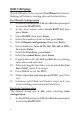
Software Installation This section provides information on how to install the Serial ATA 4-channel RAID drivers. Table of Contents Windows 98SE ........................................... page 13-14 Windows ME ............................................. page 14-15 Verify 98SE/ME Installation ........................ page 15 Windows NT 4.0 ....................................... page 15-17 Verify NT 4.0 Installation ............................. page 17 Windows 2000 ........................................
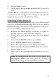
For An Existing Installation 1. Setup the RAID array prior to driver installation and boot up to Windows. 2. At the Add New Hardware Wizard, click Next. 3. Select Search for the best driver for your device option then click Next. 4. Insert the driver CD, check CD-ROM drive, uncheck the other check boxes, then click Next. 5. Click Next, then Finish. 6. Remove the driver CD and restart Windows to complete the installation.
For An Existing Installation 1. Setup the RAID array prior to driver installation and boot up to Windows. 2. At the Add New Hardware Wizard, insert the driver CD. 3. Select Automatic search for a better driver (Recommended), then click Next. 4. Accept the default entry then click OK. 5. Click Finish. 6. Remove the driver CD and restart Windows to complete the installation. When Windows resumes, go to SATARaid GUI on page 22 and install the RAID monitoring utility.
For A New Installation Important: During NT installation you will be asked to restart several times. If during any restart the RAID BIOS reports an incomplete Mirror set, disregard the message, continue with the installation, and let the Mirror rebuild on its own. This should happen only once and it's done automatically. Please do not interfere this process. Setup the RAID array prior to NT installation. 1. 2. 3. Setup the RAID array prior to NT installation. Follow Microsoft's NT installation procedure.
12. Follow on-screen instructions to complete setup for your NT version. When Windows installation completes, go to SATARaid GUI on page 22 and install the RAID monitoring utility. For An Existing Installation 1. Setup the RAID array prior to driver installation and boot up to Windows NT. 2. Double click My Computer/Control Panel/SCSI Adapters, then click on the Drivers tab. 3. Select Add… then Have Disk.... 4. Insert the driver CD, type in D:, then click OK. (Change D: to match your CD-ROM drive) 5.
Windows 2000 A new installation of Windows 2000 requires a floppy disk for the driver installation. To make this floppy disk, copy the contents of the Floppy folder, found on the driver CD, onto a blank floppy disk then follow the directions below. For A New Installation Important: During Windows 2000 installation you will be asked to restart several times.
For An Existing Installation 1. Setup the RAID array prior to driver installation and boot up to Windows. 2. When Found New Hardware Wizard appears, click Next to continue. 3. Select Search for a suitable driver for my device (recommended), then click Next. 4. Insert the driver CD, check CD-ROM drives, uncheck the other check boxes, then click Next. 5. If the Digital Signature Not Found message appears, click Yes. Our driver has been thoroughly tested for stability and compatibility.
Mirror rebuild on its own. This should happen only once and it's done automatically. Please do not interfere this process by re-configuring the RAID sets. 1. 2. 3. 4. 5. 6. 7. 8. Setup the RAID array prior to Windows installation. Follow Microsoft's Windows XP installation procedure. Restart the computer when prompted by Windows' installation. At the Windows Setup screen, press F6 to install the driver. When prompted press S to specify the location of the driver.
3. 4. 5. Accept the default entry, then click Next. At the Windows logo window, click Continue Anyway. Our driver has been thoroughly tested for stability and compatibility. Click Finish, then restart to complete the installation. When Windows resumes, go to SATARaid GUI on page 22 and install the RAID monitoring utility. To Verify Installation In Windows 2000/XP: 1. 2. 3. Right click My Computer and click Manage. Select Device Manager.
SATARaid GUI The SATARaid GUI provides the user an easy way to monitor your RAID set. It also offers administrative tools to save, copy, or send via E-mail the current configuration. Installing SATARaid GUI 1. 2. 3. 4. Place the driver installation CD-ROM into the CD-ROM drive. At the Windows desktop click Start, then Run. Type D:\Setup.exe, then click OK. (Change D: to match your CD-ROM drive) Follow the on-screen instructions to complete the installation.
Selecting each different component in the configuration tree provides specific information for that component, such as the chip. By selecting a specific channel the following information is reported.
Selecting a specific drive reports all pertinent information to that drive, including Configuration and Disk Identification information.
Selecting Sets reports on active RAID sets. By selecting the specific RAID set, such as Set 0 which is a Mirrored Set, the type of RAID set, the number of members and capacity is reported.
The Members tab reports the device identification (corresponding with the information in the BIOS) and the state of each device. Besides reporting information, the Members tab of a Mirrored Set allows the user to remove a specific drive from that set. However, a drive cannot be removed from a stripe set as this would destroy all the data.
The device identification, along with the State of each device is also reported in the Members tab window. Note that when a Mirrored-Striped set is first created, the State of the “destination” drive may report as Rebuild for as much as 30-90 minutes depending on the size of the disk. SMART and Configuration information, as well as Data Identification is again provided for each Set.
SATARaid Configuration Menu With the SATARaid GUI running, the small SATARaid icon should appear in the bottom right of the computer screen, next to the clock. By right-clicking on the icon and clicking Configure the user may configure SATARaid including customizing the settings for SMTP, E-mail, Notification, Event Level, Log File, Audio, and Popup. SMTP The SMTP server is the server that is used to send e-mails. Normally, the network administrator knows what this name is.
E-Mail Using the Email tab in the Configuration Menu, the user may set the default E-mail address and subject line to where the configuration should be sent. This, however, can be overridden at the time of sending the E-mail. Notification When different types of events occur, SATARaid may be configured to send notices to assigned individual E-mail addresses. Using the Notification tab, all E-mail addresses desired to receive the notices may be entered.
Event Level There are different types of E-mail notifications that may be sent which are set with the Event Level tab.
Log File The log file is used to store event information received from all the RAID drivers. The log file is a text file and can be viewed with Notepad or the SATARaid GUI. Use the Log File tab to set where the log file should be stored and the name of the file as well. Audio The user may set different audio alerts for the different levels of events.
Popup The popup window is a visual notification that an event occurred. The popup window can be disabled or set to popup for only certain event levels.
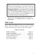
Technical Support and Warranty QUESTIONS? SIIG’s Online Support has answers! Simply visit our website at www.siig.com and click on Support. Our online support database is updated daily with new drivers and solutions. Answers to your questions could be just a few clicks away. You can also submit questions online and one of our technical support analysts will promptly respond. A lifetime manufacturer warranty supplied with this product is offered by SIIG, Inc.
About SIIG, Inc. Founded in 1985, SIIG, Inc. is a leading computer upgrade manufacturer of I/O connectivity products, including PCI & ISA serial and parallel ports, USB, Serial ATA & UltraATA controllers, FireWire (1394a/b), Networking, Sound Cards, and other accessories. SIIG is the premier one-stop source of upgrades. SIIG products offer comprehensive user manuals, many user-friendly features, and are backed by an extensive manufacturer warranty.