
Installation guide

4
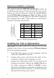
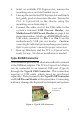
Figure 5. USB Pin-out Header Table
Installing the PCIe to ExpressCard
Important: In order for the PCIe to ExpressCard to work
properly, the driver of your existing USB host adapter
must be installed properly.
1. Turn OFF the power to your computer and all
connected peripheral devices.
2. Unplug the power cord from the back of the
computer. Remove the computer's cover.
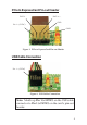
3. Connect the USB cable to the PCIe to ExpressCard
USB pin-out header. Match up +5VDC (Pin 1) on
the cable connector to Pin 1 (+5VDC) on the
ExpressCard USB pin-out header. Caution: refer to
page 3 for proper cable connection. Connecting the cable
improperly may damage your system.
Pin Assignment Pin Assignment
1 +5VDC 2 +5VDC
3 USB- (Data-) 4 USB- (Data-)
5 USB+ (Data+) 6 USB+ (Data+)
7 Ground (GND) 8 Ground (GND)
9None10Ground (GND)
Motherboard USB Pin-out Header
The typical internal USB Pin-out Header found on
motherboards consists of 9 pins arranged in 2 rows; each
header provides 2 USB ports. Match up +5VDC (Pin 1)
on the USB Cable Connector to Pin 1 or Pin 2 on the
pin-out header. Connecting the USB cable improperly
may damage the system. Please refer to your system's
manual for proper connection.