
Installation guide

2
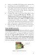
Layout
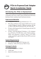
Figure 1. Board Layout
Note: Connecting to the USB Pin-out Header is
recommended. Do not connect the USB Pin-out
Header and Type-B USB Connector at the same
time. Connecting both at the same time may
damage the ExpressCard adapter and system.
USB Cable Connector
ExpressCard slot
USB Pin-out Header
Type-B USB
Connector
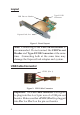
+5VDC (Pin 1)
Figure 2. USB Cable Connector
Important: The USB cable connector is designed
to plug into the 4 or 5-pin row of a USB pin-out
header. Make sure that +5VDC (Pin 1) is plugged
into Pin 1 or Pin 2 on the pin-out header.