VGA & Audio to HDMI Converter Scaler Installation Guide Introduction The VGA & Audio to HDMI Converter Scaler converts VGA and audio signals to HDMI.
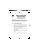
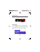
Package Contents • • • • • VGA & Audio to HDMI Converter Scaler Screw Kit and 4 rubber pads Power adapter (5V/2A) IR remote control Software CD and Installation guide Layout S/PDIF Audio In LED Indicator DIP Switch IR Sensor Push Buttons Figure 1: Front Layout • • • • 2 S/PDIF Audio In: Connect to a digital RCA S/PDIF audio source DIP Switch: F/W ( ) for firmware update; NORMAL ( ) for normal operation LED Indicator: The upper LED lights up when powered on; the lower LED lights up when signal is de
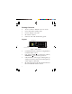
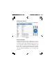
• Push Buttons (from left to right): Down, Up, Menu/Enter. See page 5 for more details. Power Jack Mini USB port Stereo Audio In HDMI Output VGA Input Figure 2: Rear Layout • • • • • Power Jack: Plug in the power adapter here Mini USB port: Connects to a USB port of a computer to control the Scaler via software. Stereo Audio In: Connects to an analog stereo audio source HDMI Output: Connects to an HDMI display VGA Input: Connects to a VGA source Hardware Installation 1. 2.
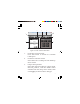
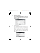
3. 4. 5. Connect the PC's analog stereo audio output to the Scaler's Stereo Audio In, or connect the PC's S/PDIF audio output to the Scaler's S/PDIF Audio In. Plug the included power adapter into the Scaler's Power Jack, then plug it into a reliable power outlet. Power on all audio/video units connected to the Scaler. The Scaler is ready to use. Application VGA and audio source 3.
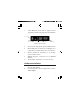
Scaler Control The Scaler can be controlled by the front panel push buttons, IR remote control or Scaler software. IR Sensor Push Buttons Push Button Press the MENU button to open the selection menu, see Figure 4. Use the UP or DOWN button to select the setting you want to change. Click Menu button to display the menu options.
IR Remote Control Point the remote control at the Scaler's IR sensor. Figure 5 Scaler Software Connect the Scaler's mini USB port to your computer's USB port using a USB cable (cable not included). Insert the included software CD to your computer, double click the Setup file and follow the on-screen instructions to install the driver. After completing the installation, double click the Scaler Software icon to launch the software.
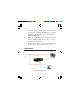
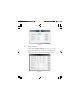
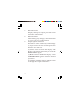
4 5 2 1 3 6 9 7 8 Figure 6: Scaler Software Main Menu 1. 2. 3. COM Port search button: Click the button to search for available COM ports. COM Port selection menu: Select the Scaler's COM port from the drop down menu. Output Setup button: Select the output resolution, output mode, default pattern, and the EDID audio channel from the drop down menu, then click Apply to enforce these changes.
Figure 7 4. Image button: Click the Image button to set up your preferred display contrast, brightness, saturation, hue and other related values.
5. Adjustment Button: Click the Adjustment Button to adjust the screen size, change the aspect ratio or other display settings. Figure 9 6. System Button: Click System button, then click Get to view the current input resolution, or click Factory Reset to set the Scaler back to the default settings. The firmware can also be updated here. Please refer to the instructions on page 11.
7. 8. 9. 10 Resolution info: Displays the input/output port and screen resolution information. Refresh button: After making any changes, click this button to view your new configuration. Output Quick Selection: Shortcuts to some commonly used settings: (1) Aspect ratio: Click to switch aspect ratio between 4:3 and 16:9. (2) Freeze: Click to freeze the display. The display will remain still until you click the Freeze button again. (3) Blank: Click to disable the display.
Firmware Update Note: If the Scaler Software is not installed, go to Scaler Software on page 6 now and follow the instructions to install it. Otherwise, follow the instruction below to update the firmware. 1. 2. 3. 4. 5. 6. 7. Connect the Scaler to your computer using a USB cable (cable not included), double click the Scaler software icon. Enter the Scaler software main menu, select a COM port and click Refresh to make the connection. Click System button, then click Firmware Update.
OSD Menu Refer to Table 1 for the various OSD viewing options.
1st Tier Option 2nd Tier Option Contrast 0~255 (Default 128) Brightness 0~255 (Default 128) Saturation 0~255 (Default 128) Hue 0~255 (Default 128) B/W Extension Image Range Off (Default) On Off (Default) Color Tone Skin Green Typ (Default) Edge Enhance Mid Max Off Sharpness 0-127 (Default 0) In-Sync Info System Firmware Version V1.
1st Tier Option 2nd Tier Option Range Under/Over Scan -50%~50% (Default Off) Aspect Ratio Adjustment H-Mirror V-Mirror 16:9 (Default) 4:3 Off (Default) On Off (Default) On Input H Adj 0~200 (Default 0) Input V Adj 0~100 (Default 0) Table 1 Supported Video Resolution Table 2 14
Technical Support and Warranty QUESTIONS? SIIG’ s Online Support has answers! Simply visit our web site at www.siig.com and click Support. Our online support database is updated daily with new drivers and solutions. Answers to your questions could be just a few clicks away. You can also submit questions online and a technical support analyst will promptly respond. SIIG offers a 3-year manufacturer warranty with this product.
About SIIG, Inc. Founded in 1985, SIIG, Inc. is a leading manufacturer of IT connectivity solutions (including Serial ATA and Ultra ATA Controllers, FireWire, USB, and legacy I/O adapters) that bridge the connection between Desktop/ Notebook systems and external peripherals. SIIG continues to grow by adding A/V and Digital Signage connectivity solutions to our extensive portfolio.