
Installation guide


2
Package Contents
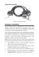
• DP CyberSerial 4S PCIe adapter and spare enhanced
low profile bracket
• 4-port fanout cable & "Y" split power cable
• Driver CD and quick installation guide
Layout
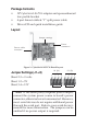
Figure 1: CyberSerial 4S PCIe Board Layout
Jumper Settings (J1-J4)
Short 2-3 = 0 volts
Short 1-2 = 5V
Short 3-4 = 12V
* Note: If the serial port(s) requires power output,
connect the system power source to board's power
connector, otherwise leave it unconnected. However,
most serial devices do not require additional power
through the serial port. Refer to your serial device's
manual for more information. The jumpers can be
omitted if no power output is required.
Power
connector*
Fanout cable
connector
Jumper settings
1234 234
S1 (J1)
1
S3 (J3)
S4 (J4)
S2 (J2)