
User`s manual


54
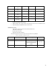
Wait State Control Register 1 (WCR1)
Wait state control register 1 (WCR1) specifies the idle time between area changes and a read
to a write in the same area.
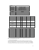
Wait State Control Register 2 (WCR2)
Wait state control register 2 (WCR2) is a 32-bit read/write register that specifies the number
of wait state cycles inserted for each area. It also specifies the pitch of data access for burst
memory accesses. This allows direct connection of even low-speed memories without an
external circuit. WCR2 is initialized to H'FFFFFFFF by a power-on reset. It is not initialized
by a manual reset or by standby mode.
Wait state control register 1 WCR1 H'FFFFFF64 0x3cf3
bit15: WAIT Sampling at rising edge of CKIO ( 0 )
bit14: Reserved: read as 0. ( 0 )
bit13-12: Area 6 Intercycle Idle = 3 ( 1 1 )
bit11-10: Area 5 Intercycle Idle = 3 ( 1 1 )
bit9-8: Area 4 Intercycle Idle = 0 ( 0 0 )
bit7-6: Area 3 Intercycle Idle = 3 ( 1 1 )
bit5-4: Area 2 Intercycle Idle = 3 ( 1 1 )
bit3-2: Reserved: read as 0. ( 0 0 )
bit1-0: Area 0 Intercycle Idle = 3 ( 1 1 )
Wait state control register 2 WCR2 H'FFFFFF66 0xfd7e
bit15-13: A6W - CS6 wait control: 10 states ( 1 1 1 )
bit12: A5W - CS5 wait control: 10 states ( 1 )
bit11-10: A5W - CS5 wait control: 10 states ( 1 1 )
bit9-8: A4W - CS4 wait control: 2 states ( 0 1 )
bit9: A4W - CS4 wait control: 2 states ( 0 )
bit6-5: A3W - CS3 SDRAM CAS latency: 3 states ( 1 1 )
bit4: A2W - CS2 wait control: 3 states ( 1 )
bit3: A2W - CS2 wait control: 3 states ( 1 )
bit2-0: A0W - CS0 wait control: 8 states ( 1 1 0 )