
User`s manual


49
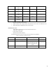
PINT10 AutoPC Interrupt
conn.
AUTOINT2 Low
PINT11 AutoPC Interrupt
conn.
AUTOINT3 Low
PINT12 AutoPC Interrupt
conn.
AUTOINT4 Low
PINT13 AutoPC Interrupt
conn.
AUTOINT5 Low
PINT14 AutoPC Interrupt
conn.
AUTOINT6 Low
PINT15 AutoPC Interrupt
connector.
AUTOINT7 Low
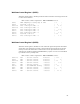
Hardware Initialization Requirements
• SDRAM address mux. timing should be setup identical on the V320 versus SH7709A/7729
• SH3 should float the SDRAM bus when not bus master
HD64465 Area: Area 4
2.Bus width: Longword (32 bits) size and Little Endian access.
3.Idle state: No idle cycles
4.Wait state: 2 wait states
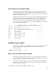
SH7709A/7729 Mode Selections
The following mode selections are hard-wired on the board (except MD3/4).
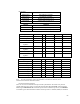
Table 40: SH7709A/7729 Mode selections
Mode Bit Function Setting Logic Level
MD2/1/0 Clock Setup Int. Clk.= 4x Ext. Clk. 111
MD4/MD3 Word Size of Address Area 0 Boot selectable between 8 and
32 bits. Determined by Switch
SW1 in conjunction with
CPLD.
8 = 01
32 = 11
MD5 Little/Big Endian Little Endian 1