
User`s manual


29
Microsoft has a reference platform that is used for running Windows CE inside an automobile
called Auto PC. It consists of a CPU and a support card attached to a PCI bus.
A HARP Board may electrically connect to the Auto PC platform by adding an additional
Molex connector (part number 52584-1209) to the CompactPCI bus. This connector is placed
on the underside of the PCB and runs parallel to the board just in front of the CompactPCI
connectors.
With the “A” side of the connector closest to the edge Compact Flash PCI connector, the pin
out follows the standard PCI specification version 2.1.
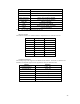
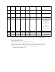
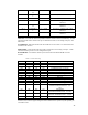
Table 11: Auto PC Connector Pin-out
A-Side B-Side
Pin Signal Pin Signal
1 TRST 1 -12V
2 +12V 2 TCK
3 TMS 3 Ground
… … … …
59 +5V 59 +5V
60 +5V 60 +5V
The Auto PC also requires the ability to wake up with any of eight low-true wake-up event
interrupts.
Note: The Auto PC connector conflicts mechanically with CompactPCI application so
only one option can be provided.
Hitachi 200 pin Local Bus Connector
Supports the 200 pin Hitachi Local Bus extender.
Hitachi 140 pin Local Bus Connector
Supports the 140 pin buffered local bus used to connect the Tahoe and other daughter boards.
Four Wire Touch screen input
A Four-Wire Touch Screen Input is supported by the HD64465. The drive control signals are
provided by the GPIO[3:1] signals and the return A/D is supported by the TSPX,TSMX,
TSPY, and TSMY signals.
All circuitry and support is provided on the Tahoe board.
Power Supply
Power to the Key West/Tahoe is supplied either through an ATX power connector in stand-
alone mode, or by the CompactPCI chassis. Power supplied on the ATX connector is 3.3 V,
+/-5 V, +/-12 V.
The SH7709A/7729 requires 1.8 V for the CPU core and 3.3 V for the I/O. The SDRAM runs
at 3.3 V. The main CPLD runs at 3.3 V, the PCI, PCI arbiter, boot EPROM, and flash runs at
5.0 V. The compact PCI connector requires +/- 12 V.
Bus Interface
SDRAM Interface