
User`s manual

27
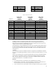
43 P18 44 P19
45 GND 46 P21
47 P20 48 P23
49 P22 50 GND
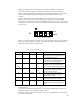
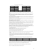
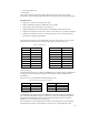
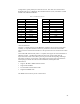
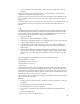
Table 10: LCD Data Format
Data Pin
Citizen Color
K6488L-FF
640x480
scan-line start
Citizen B/W
G6485H-FF
640x480
Single Scan
Sharp Color
LM8V30/1
640x480
scan-line start
P0 UD7 – Upper Scan Red 0 -- UD7 – Upper Scan Red 0
P1 UD6 – Upper Scan Green 0 -- UD6 – Upper Scan Green 0
P2 UD5 – Upper Scan Blue 0 -- UD5 – Upper Scan Blue 0
P3 UD4 – Upper Scan Red 1 -- UD4 – Upper Scan Red 1
P4 LD7 – Lower Scan Red 0 -- LD7 – Lower Scan Red 0
P5 LD6 – Lower Scan Green 0 -- LD6 – Lower Scan Green 0
P6 LD5 – Lower Scan Blue 0 -- LD5 – Lower Scan Blue 0
P7 LD4 – Lower Scan Red 1 -- LD4 – Lower Scan Red 1
P8 UD3 – Upper Scan Green 1 Pixel 0 (Upper leftmost) UD3 – Upper Scan Green 1
P9 UD2 – Upper Scan Blue 1 Pixel 1 UD2 – Upper Scan Blue 1
P10 UD1 – Upper Scan Red 2 Pixel 2 UD1 – Upper Scan Red 2
P11 UD0 – Upper Scan Green 2 Pixel 3 UD0 – Upper Scan Green 2
P12 LD3 – Lower Scan Green 1 Pixel 4 LD3 – Lower Scan Green 1
P13 LD2 – Lower Scan Blue 1 Pixel 5 LD2 – Lower Scan Blue 1
P14 LD1 – Lower Scan Red 2 Pixel 6 LD1 – Lower Scan Red 2
P15 LD0 – Lower Scan Blue 2 Pixel 7 LD0 – Lower Scan Blue 2
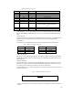
The LCD panel must either allow the VSENSE pin to float or must drive it to ground in order
to indicate the desired voltages for signaling panel. When the LCD panel grounds the
VSENSE pin, the LCD controller must drive and receive the voltage levels 0V and 3.3V.
When the LCD panel floats the VSENSE pin, the LCD controller must drive and receive the
voltage levels 0V and 5V (4V minimum high voltage).
The signals P0-P15, LOAD, FRAME and CP will be source terminated with 22 Ohm resistors
in series and 56Pf in parallel with the connector side of the resistor. Weak pull-down resistors
should be added to ENAVEE, ENAVDD and ENABKL to insure that the panel remains off
during power-on.
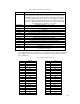
PCMCIA
The Tahoe board contains two PCMCIA slots that are supported by the HD64465 companion
chip. Slot 0 of the double-high PCMCIA connector is located on the bottom and slot 1 is on top
of slot 0.
The PC Card Controller (PCC) controls the internal buffers, interrupts, and PCMCIA-defined
ports of the PC card interfaces, which is connected to the Intelligent Peripheral Controller
(IPC). The PCC enables two slots of the PC cards that are compliant with the PCMCIA PC
Card Specification Release 2.1 and JEIDA Version 4.2
Features:
• Two channels of the PC card interfaces can be simultaneously controlled
• Supports memory card interface, and I/O and Memory card interface, which function as
PC card interfaces and are connected to physical memory areas 5 and 6.
• Area 6 is allocated to PC Card Channel 0 (PCC0) and supports memory and I/O interfaces.