
User`s manual

26
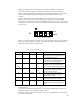
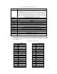
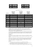
Table 8 HARP LCD Header Signal Definitions
Name Function
DF The DF signal is used on some LCD panels for internal biasing. It is a
clocking signal that changes state at the beginning of each new frame while
the FRAME signal is active. During all even numbered frames it will be a '1'
and during odd numbered frames it will be a '0'. An example of a panel that
requires this signal is the Sharp LM48014F where the datasheet refers to the
signal as M. The implementation of this signal is not required. If this signal
is not implemented, it should be a “no connect”.
ENABKL Enable Back-light, H = On, L = Off
ENAVDD Enable VDD supply on LCD panel, H = On, L = Off
ENAVEE Enable VEE supply on LCD panel, H = On, L = Off
P0-23 LCD Data
FRAME LCD Start of Frame signal. High pulse at start of each LCD frame.
LOAD LCD Start of Line signal. High pulse at start of each LCD line.
XLEFT Resistive touch panel X-Left conductor.
XRIGHT Resistive touch panel X-Right conductor.
YLEFT Resistive touch panel Y-Upper conductor.
YRIGHT Resistive touch panel Y-Lower conductor.
CP LCD data “dot clock”. High pulse for each data transfer.
V12V DC Supply 12V +/-5%, 80 mA
V5V DC Supply 5V +/- 5%, 2A
V3V DC Supply 3.3V +/- 5%, 2A
VSENSE Binary indicator from panel to controller for preferred signal levels.
H = 0V/5V. L = 0V/3.3V.
The voltage levels driven for signals P0-P15, CP, LOAD, FRAME, DF, ENAVEE, ENAVDD
and ENABKL must be driven as indicated by the VSENSE pin. The VSENSE is pulled up
with a 10KΩ resistor.
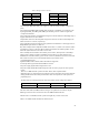
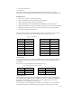
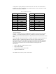
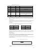
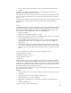
Table 9: HARP LCD Header Pin-out
1 VSENSE 2 V12V
3 ENABKL 4 GND
5 V3V 6 V3V
7 ENAVDD 8 V5V
9 V5V 10 ENAVEE
11 DF 12 GND
13 P0 14 P1
15 P2 16 P3
17 P8 18 P9
19 P10 20 P11
21 GND 22 P4
23 P5 24 P6
25 P7 26 P12
27 P13 28 P14
29 P15
30
GND
31 FRAME 32 LOAD
33 GND 34 CP
35 GND 36 XLEFT
37 XRIGHT 38 YUPPER
39 YLOWER 40 GND
41 P16 42 P17