
User`s manual

25
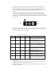
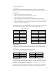
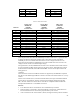
Table 6: IrDA connector Pin-out
Pin Name Direction Function
1 TX I Transmit data
2 SEL1/ID1 I/O I/O Pin for identification
3 GND O Ground
4 VCC O +5V or +3.3V
5 SEL2/ID2 I/O I/O Pin for mode select and identification.
6 ID3 I/O I/O Pin for identification
7 IRRX2 O Receive data from FIR receiver.
8 RX1 O Receive data from SIR if (SEL2 is low), or
from demodulated 38KHz IR if SEL2 is
high.
9 NC
10 NC
When the ID pins are in an input state they return an ID that indicates the type of IR “dongle”
attached. The SDB has 100KΩ pull-up resistors (to VCC) on all of the identification (IDn)
pins.
PS/2 Mouse Port
A PS/2 mouse interface is provided by the HD64465 on the Tahoe board. It is implemented as
a Register Interface peripheral and all protocols and timing conform to IBM-PC PS/2
specifications.
The connector is a 6-pin Mini-DIN type and uses the standard PC pin-out shown below.
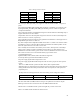
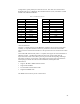
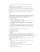
Table 7: Mouse PS/2 Connector Pin-out
Pin Name Pin Name
1 MDAT 4 VCC
2 NC 5 MCLK
3 GND 6 NC
LCD Panel Support
The MQ-200 video controller chip supports the LCD video output. There will be two default
LCD headers available on Board 2, and the option to scramble the wire hookup to the second
header if desired.
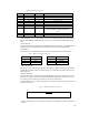
HARP LCD Header
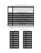
The first header (JP33) is defined to meet the HARP LCD connector specification. It is a 50
pin connector, with the first 40 pins supporting the HARP specification. The connector uses a
0.1” spacing, ribbon cable style connector. Its pin-outs are noted below.
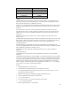
The 50-pin header is a 0.1” ribbon cable header, mounted on the Tahoe board. The top view of
the header pin order is:
Figure 2: HARP LCD Connector pin-out
49 1
50 2
The second header (JP35) is a custom LCD connector. Contact Hitachi if more information is
required.