
User`s manual


17
3.5 Downloading “bootrom.hex” Image to the Target
There are several methods available to download images to the target. We will use DMON’s “LE”
command in conjunction with a TFTP server. Tftpd32 is a freeware TFTP server and is included in the
support CD-ROM. It is also available for download on the Platform Support web page at
http://ftp.hsa.hitachi.com/netshare/capp01/
as well as other locations on the Internet. Simply extract the ZIP
file to a known location.
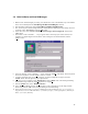
Setup TFTP Server
1. Start the TFTP server by executing tftpd32.exe. Click the “S
ettings” button to bring up the
“Tftpd32: Settings” dialog. In the “Base Directory” field, enter “c:\release\” or the appropriate
directory. Click the “OK” button to close the dialog.
2. The “bootrom.hex” file should appear in the listing when the “Show D
ir” button is clicked.
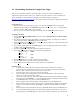
Setup HyperTerminal
1. From the Start→
→→
→P
rograms→
→→
→Tornado2 menu, select either VxWorks COM1 or VxWorks COM2
as appropriate.
2. This will execute HyperTerminal. By default it is connected at 9600bps. To change this, we will first
need to disconnect. Select “D
isconnect” from the “Call” menu.
3. Select “Pr
operties” from the “File” menu. A dialog may appear asking you to confirm the modem/port
selection. If so, click the “OK” button.
4. The properties dialog appears. In the “Connect To” tab, select the appropriate serial port (“COM1” or
“COM2”) in the “Con
nect using” field.
5. Click the “Conf
igure…” button to configure the serial port properties.
6. In the serial port’s properties dialog, select the following configuration:
B
its per second: 57600
D
ata bits: 8
P
arity: None
S
top bits: 1
F
low Control: None
7. Click the “OK” button to close the serial port properties dialog.
8. Click the “OK” button to close the connection’s properties dialog.
9. Select “C
all” from the “Call” menu to reconnect with the new configuration.
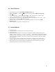
Setup the Target
1. Attach the null modem serial cable (supplied) from the target to the host PC’s serial port.
2. Attach an Ethernet network cable to the target. This can be from a network hub via a standard
Ethernet cable, or from the host PC directly via a crossover cable.
3. Attach the power supply to the power connector of the target.
4. Ensure that the board is configured to boot from the boot ROM (SW1-1 ON) and that flash
memory is not write-protected (SW1-3 OFF)
5. Turn on the power supply and verify that the DMON monitor has booted successfully. The debug
hex display should read “READY ..” and a prompt should appear in the HyperTerminal window.
6. At the DMON prompt, type “le” and press the <Enter> key.
7. When prompted, assign a valid IP address to the target board. Press the <Enter> key.
8. When prompted, enter the IP address of the host PC. This information is displayed in the Tftpd32
window or can be obtained with the “ipconfig” command at the DOS/Windows command
prompt.
9. When prompted, enter the filename of the image: “bootrom.hex” and press the <Enter> key.
10. After successfully loading the image, proceed with programming the flash memory. Type “p” at
the prompt and press the <Enter> key. The procedure should be complete in just a few seconds.