NOTICE SignWarehouse.com reserves the right to modify the information contained in this user manual at any time without prior notice; un-authorized modification, copying distribution or display is prohibited. All comments, queries or suggestions concerning this manual please consult with your local dealer. Updates to this and other useful articles can be found at www.signwarehouse.
Important Information Thank you for purchasing the Vinyl Express Enduracut Cutting Plotter. Before you use the cutting plotter, please make sure that you have read the Safety instructions and precautions below. SAFETY PRECAUTIONS! ¾ For safety concern, please always hold the cutter firmly from the bottom while moving it. Do not move the cutter by clasping the depression area on both sides. O (correct) X (Incorrect) ¾ Do not shake or drop the blade holder, a blade tip can fly out.
Important Information 1. General Information 1.1 Package Items 1-1 1.2 Product Features 1-1 1.3 The Appearance 1-2 2. Installation 2.1 Precaution 2-1 2.2 Blade Installation 2 2.3 Media Loading 2 2.4 Cable Connections 2 3. Operation 3.1 The Control Panel 3-1 3.2 Cutter Driver Options 3-2 3.3 File Up-loader 3-5 3.4 Data Transmission 3-6 4. Basic Maintenance 4.1 Cleaning the cutting Plotter 4-1 4.2 Cleaning the Grid Drum 4-1 4.3 Cleaning the Pinch Rollers 4-2 5. Trouble Shooting 5.
1. General Information 1.1 Package Items The package of Enduracut-60 contents the items listed below, please check carefully. If you find any item missing, please consult your local dealer for further assistance. Item Cutting Plotter Accessories 1. Cutting Pad 2. AC Power Cord Quantity 1 Set 1 Set 3. Desktop Support Brackets 7. Tweezers 5. Paper Slitter 6. RS-232 Cable 1.2 Product Features The followings are the main features of the Enduracut cutting plotters: ‧ Serial interface.
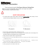
1.3 The Appearance (Enduracut) 1.3.1 The Front View 【Figure 1-1 】 A Primary Pinch Roller To help hold the media during cutting. C Alignment Ruler To align media with clear guideline marks D Tool Carriage To help perform cutting job with installed blade or pen. F Platen The surface for holding and supporting media while in operation. H Consist of 10 control keys and 6 LED lights.
1.3.2 The Back View J Grid Drum To move media back and forth in operation. 1.3.3 The Side Views 【Figure 1-3 】 【Figure 1-4 】 K L M N Object AC Power Connector Fuse Power Switch USB Connector Description To insert the AC power cord. 3Amp. To turn on or off the machine. To connect the machine and a computer through a USB cable. O Serial Interface Connector To connect the machine and a computer through a RS-232 cable.
2. Installation 2.1 Precaution Please read below information carefully before you start installation. Notice 1 ¾ Make sure the power switch is off before installing the cutting plotter. ¾ Carefully handle the cutter to prevent any injuries. Notice 2 Choosing a proper place before setting up the cutting plotter Before installing your cutting plotter, select a suitable location, which meets the following conditions. ¾ The machine can be approached easily from any direction.
2.2 Blade Installation Figure 2-12 is the illustrator of the blade holder. Insert a blade into the bottom of the blade holder and remove the blade by pushing the pin. Make sure that your fingers are away from the blade tip. Adjustment depth knob Pin Outward ring Step 1 Install blade (Figure 2-13). Step 2 Push the blade to the bottom of the blade holder (Figure 2-14). Step 3 Adjust the blade tip to suitable length by screwing “Blade tip adjustment screw” clockwise or countclockwise. (Figure 2-15).
Step 4 Insert the blade holder into tool carriage. Please note the outward ring of the holder must put into the grooves of carriage firmly (see Figure 2-16), fasten the case (Figure 2-17). Step 5 Use the reversing steps to remove the blade holder. Step 6 Eject the blade: Push “Blade eject pin” to eject blade when the blade needs to be replaced.
2.3 Media Loading 2.3.1 Loading the Sheet Media To load the media properly, please follow the below procedures: Step 1 Lift the 2 levers at the back side of cutter to raise pinch rollers (Figure 2-18). Step 2 Load your media on the platen and slide it under the pinch rollers from either the front side or the backside. The alignment rulers on the platen extension will help you to adjust the media precisely (Figure 2-19).
Step 3 Then move the pinch rollers manually to the proper position. Be sure the pinch rollers must be positioned above the grid drum. The white marks on the main beam will remind you where the grid drums are (Figure 2-20).
Step 4 Push the lever backward to lower down the pinch rollers (Figure 2-21). Step 5 After turn on the power, the tool carriage will measure the size of the media automatically. And the plotting cutter begins to work. (X)Incorrect 2.3.2 Loading the Roll Media You can use the desktop media support system for roll media. Please refer to Chapter 2.2.2~2.3 for hardware setup, and Chapter 2.5.1 for media loading. 2.
2.4.1 USB Interface Enduracut can connect to your computers USB port using a Keyspan Highspeed USB Serial Adaptor. Caution!! • DO NOT plug USB cable into Enduracut Cutter. That port is for loading firmware at the factory only. 2.4.2 RS-232 Interface . Connecting to the RS-232 (Serial) Port 1 For IBM PC, PS/2 users or compatibles, connect the RS-232C cable to the serial connector of the assigned serial port (COM1 or COM2) of your host computer.
3. Operation 3.1 The Control Panel 3.1.1 The Outline of control panel Figure 3-1 Key Function POWER LED To indicate the power status ( light up: power on; light off: power off ) ERROR LED To indicate the error status ( light up: error; light off: normal ) ON/OFF LINE To switch modes or stop cutting job (light up: on-line; light off: offline) While in on-line mode: only ON/OFF LINE and PAUSE keys activated While in off-line mode: the settings in VLCD can be adjusted.
Step 1 Move the carriage to a new position. Step 2 Press the ORIGIN SET button to reset origin. 3.1.3 Cut Test Step 1 After sizing, press the ON/OFF LINE button to set as off-line mode. Step 2 Move the carriage to a preferred position. Step 3 Press CUT TEST button to perform. 3.1.4 Repeat Step 1 Press the ON/OFF LINE button to set as off-line mode. Step 2 Press the REPEAT button to perform re-plot function starting at the position where the carriage locates.
3.2 Data Transmission There are two options to transmit the data from the computer to the cutting plotter: Option 1: With proper interface settings, the data can be transmitted from your application software package to the cutting plotters directly. Option 2: Most cutting software packages are able to emulate HP-GL or HP-GL/2 commands, therefore, Use DOS commands like TYPE or PRINT to output your file. As long as the file is HP-GL or HPGL/2 format, the cutting plotter can output the data precisely.
4. Basic Maintenance This chapter explains the basic maintenance (i.e. cleaning the cutting plotter) required for the cutting plotter. Except for the steps mentioned below, all the other maintenances must be performed by a qualified service technician. 4.1 Cleaning the cutting plotter In order to keep the cutting plotter under good conditions and have the best performance, you need to clean the machine properly and regularly. Precaution in Cleaning . Unplug the cutting plotter before cleaning. .
4.3 Cleaning the Pinch Rollers If the pinch rollers need a thorough cleaning, use a lint-free cloth or cotton swab to wipe away the accumulated dust from the rubber portion of the pinch rollers. To prevent the pinch rollers from rotating while cleaning, use your fingers to hold the pinch rollers in place. Use a lint-free cloth or cotton swab rinsed with alcohol to remove the embedded or persistent dust.
5. Trouble Shooting This chapter helps you to correct some common problems you may come across. Prior to getting into the details of this chapter, please be sure that your application environment is compatible with the cutting plotter. Note: Before contacting your local dealer, please make sure that the problems are coming from your cutting plotter, not from the communication between the computer and cutting plotter or from a malfunction in your computer or software.
5.2.1 Warning Indicators When the ERROR LED flashes (as shown below), take the necessary actions according to the following instructions. When the problems are solved, the ERROR LED will turn off automatically. Pressing the ON/OFF LINE button can also turn off the ERROR LED.
Warning 5 Communication error Check that the serial/USB cable has been connected to the cutting plotter and computer properly. If so, then check whether the interface settings are correct. Check that the communication settings in your PC are the same as the ones on your cutting plotter (for example – 9600bps, no parity, 8 bits, 1 stop bit). Then, press ON/OFF Line key to switch back to On Line mode.
5.
Appendix -Enduracut Specification Model Enduracut Max. Cutting Width 605mm (23.75") Max. Media Width 719mm (28.3") Material Thickness 0.8mm Max. Cutting Force 250g Max. Cutting Speed(Diagonal) 400 mm /sec Software Resolution 0.025 mm Repeatability ±0.