
User guide

• www.signwarehouse.com • SignWarehouse, Inc. • 2614 Texoma Drive, Denison, TX 75020
•Toll Free Phone: 1-800-899-5655 •Local Phone: 903-462-7700 •Fax: 1-800-966-6834
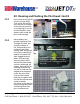
29: Maintenance Station Assembly: Cont’d
Once the side cover is removed, you will have easy access to the fixed-position
maintenance station assembly. To remove it, you will need to unscrew five phillips-
head screws and detach the electrical connector behind the assembly.
29.3
29.4
29.5
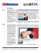
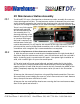
First, unscrew the single
phillips-head screw facing
upward (Fig 1). This screw
secures the metal tab that
holds the side bracket in
place. After removing this
screw, lift the side bracket
and set it aside.
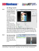
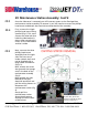
Next, unscrew the three
phillips-head screws
accessible from the right
side. The front one is
inside a plastic shaft and
can be reached with a
long handle screwdriver
(Fig 2, 3).
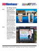
Next, remove the screw
that grounds the orange
wire in the back of the
maintenance assembly
(Fig 3).
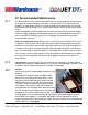
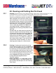
Now squeeze the side
bracket of the gray
electrical connector and
pull the wiring harness to
disconnect the
maintenance station (Fig
4).
Gently pull the
maintenance station
forward and remove
through the front ‘door’
of the printer.
Grasp the connector
by the sides, pinch the
bracket and pull the wire
harness toward you.
Fig.1
Fig.2
Fig.3
Fig.4