User Manual User Manual https://www.signwarehouse.com/blog-support/ NOTICE SignWarehouse Inc. reserves the right to modify the information contained in this user manual at any time without prior notice; un-authorized modification, copying distribution or display is prohibited. All comments, queries or suggestions concerning this manual please consult with your local dealer. 2614 Texoma Drive Denison, TX 75020 • 980 Contract St.
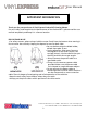
User Manual IMPORTANT INFORMATION Thank you for your purchase of Vinyl Express EnduraCUT2 Cutting Plotter. For your safety and to optimize the performance of the EnduraCUT 2, please read the user manual completely and keep it in a correct location. PRECAUTIONS IN USE • For safety concern, please always hold the cutter firmly from the bottom when moving it. Do not move the cutter by clasping the depression area on both sides. • Do not shake or drop the blade holder, a blade tip maybe fly out.
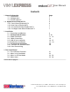
User Manual Contents 1. General Information Page 1.1 Introduction 5 1.2 Package Items 5 1.3 Product Features 6 1.4 Appearance of EnduraCUT 2 6 1.4.1 Front View of EnduraCUT 2 6 1.4.2 Rear View of EnduraCUT 2 7 1.4.3 The Left-hand Side of EnduraCUT 2 7 1.4.4 The Right-hand Side of EnduraCUT 2 7 2. Installation 2.1 Precautions and Notices 8 2.2 Desktop Roller Brackets 9 10 2.3 Blade Installation 11 - 13 2.4 Cable Connections 14 2.5.
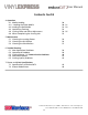
User Manual Contents Cont’d 4. Operation 4.1 Media Loading 4.1.1 Loading the Sheet Media 4.2 Loading the Roll Media 4.3 Optimizing Tracking 4.4 Cutting Force and Offset Adjustment 4.4 When Completing the Cutting Job 30 30 - 31 32 - 33 33 34 - 35 35 5. Maintenance 5.1 Cleaning the cutting Plotter 5.2 Cleaning the Grit Rollers 5.3 Cleaning the Pinch Rollers 36 36 37 6. Trouble Shooting 6.1 Non-Operational Problems 6.
User Manual Chapter 1: General Information 1.1 Introduction EnduraCUT 2 cutting plotters have been designed to produce computer-generated images on sheets or rolls of vinyl media. This manual covers the Vinyl Express EnduraCUT 2 series cutting plotter: acceptable media widths range from 2.76”(70mm) ~ 28.3”(719mm) 1.2 Package Items The EnduraCUT 2 is shipped with the items listed below. Please check your package carefully.
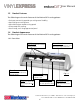
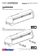
User Manual 1.3 Product Features The following are the main features of the EnduraCUT 2 cutting plotter: • Dual-port connectivity provides you with greater flexibility. • Up to 400-gram cutting force. • Up to 600mm/per second cutting speed. • Guaranteed 16ft tracking. • User-friendly, multi-language control panel 1.4 Product Appearance The following are the main features of the EnduraCUT 2 cutting plotter: 1.4.1 Front View Grid Drums move the media back and forth during operation.
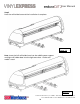
User Manual 1.4.2 The Rear View (Figure 1-2) Pinch Rollers Holds the media during cutting Lever raises or lowers the pinch rollers. Fig 1-2 1.4.3 The Left-Side View (Figure 1-3) Fuse -3Amp. 1.4.4 Right-Side View (Figure 1-4) Fig 1-3 USB Connector AC Power Connector Fig 1-4 Used to connect the cutting plotter to a computer through a USB cable. Power Switch -On when switches to [I]; Off to [O].
User Manual Chapter 2: Installation 2.1 Precautions Notice 1 • Carefully handle the cutter to prevent any injuries. • Make sure the power switch is off before installing the cutting plotter. Notice 2 A proper place for installation the cutting plotter Please select a proper location that meets the following conditions: • The machine can be approached easily from any direction. • Keep at least 2feet (60 cm) of clear space in front and behind the machine.
User Manual 2.2 Desktop Roller Brackets Step 1 Check three spacer supports on the back of the machine. Figure 2-1 Step 2 Insert the left and right roll holder base into the spacer supports on the left and right side when 2 inches roll media is used. Figure 2-2 2614 Texoma Drive Denison, TX 75020 • 980 Contract St.
User Manual Step 3 Press the roll holder base and the installation is complete. Figure 2-3 Note: Insert the left roll holder base into the middle spacer support and right roll holder base into the right one when 1 inches roll media is used. Figure 2-4 2614 Texoma Drive Denison, TX 75020 • 980 Contract St.
User Manual 2.3 Blade Installation Caution! • Do not touch the tip of the blade with your fingers! Notice! The blade is a consumable item, which will affect the cutting quality significantly. Please replace with a new blade when having the following situations: 1. The tip of blade is broken. 2. The cutting traces are not as good as they were. 3. Uncut area remains the same even the blade force has been raised significantly Figure 2-5 is the picture of the blade holder.
User Manual 2.3 Blade Installation 1: Install Blade. (Figure 2-6) Figure 2-6 2: Push the blade to the bottom of the blade holder. (Figure 2-7) Figure 2-7 3. Adjust the blade tip to suitable length by rotating “Blade depth adjustment screw” clockwise or counterclockwise. (Figure 2-8) Tips: “The proper length” means the blade length is about 0.1mm more than film’s thickness. For example, if the thickness of film is 0.5mm, then the blade length is properly adjusted to 0.
User Manual 4. Insert the blade holder into tool carriage. Please note the outward ring of the holder must put into the groove of carriage firmly (Figure 2-9) and lock the grip. (Figure 2-10) Figure 2-10 Figure 2-9 5. Reverse steps mentioned above to remove the blade holder. 6. Press the push-pin to remove the blade from the blade holder when replacing blade. (Figure 2-11) Figure 2-11 2614 Texoma Drive Denison, TX 75020 • 980 Contract St.
User Manual 2.4 Cable Connectioins The EnduraCUT 2 communicates with a computer through USB (Universal Serial Bus) or Serial port (RS-232C). This chapter shows you how to connect the cutting plotter to a host computer and how to set up the computer/cutting plotter interconnection. NOTE! When the USB connection is enabled, the serial port is automatically disabled. Serial Port USB Port Figure 2-12 2.5.
User Manual USB Driver Installation Cont’d Connecting the plotter 1. Turn on the machine. 2. Connect the USB connector to the machine and then USB driver will installed automatically. It will take a few minutes to find the device. Please DO NOT disconnect the USB cable until the installation has completed. 3. You can double click the USB icon on the taskbar to make sure the USB device is detected (Fig 2-13). Figure 2-13 2.
User Manual 2.6 Setting up Your EnduraCUT 2 In LXI 1: Turn plotter on and connect USB port to your PC. 2: Then Open LXI software, draw a box or add text to the screen and click the Cut/Plot Icon, or click File/Cut-Plot to open the LXI Cut/Plot Window. When Production Manager opens, click Setup. Then from the drop-down menu, click Add Setup (Fig 2-14) Figure 2-14 3: In the Add Setup window, you will be prompted to “choose a device” (Fig 2-15).
User Manual 4: After you have selected the make and model of the cutter, click Next at the bottom of the Add Setup window. The next screen in the Add Setup window will prompt you to choose a port by asking “How is your enduraCUT 2S connected to your computer?”. Click the arrow to show the drop-down menu (Fig 2-18) and, from the list of ports, choose USB_Printer_1 .
User Manual 6: If the plotter did not respond to the test cut (or if some other device was activated, you must change the port setting to the correct one for the plotter (or connect the plotter to a different USB port). To change the USB port setting, right-click on “enduraCUT2S _USB_Printer_1” (just above “EnduraCUT2S”. From the pop-up menu, select Change Port (Fig 2-20). Then, from the menu of available ports, select a different USB printer port (Fig 2-21).
User Manual 2.7.1 USB Driver Un-Installation If you have to un-install the USB driver after it has been installed on your PC, or if you need to install a newer version, the existing driver must be removed completely before you can re-nstall the current driver or install a newer version. Please refer to below steps 1: Click the Windows Start button and open the Devices and Printers folder. Right-click on the printer (EnduraCUT 2 or Expert-Pro 60) and, from the drop-down menu, click Delete.
User Manual 4: Find the Expert Pro 60 in the list of print devices, click to highight it, then click Remove and OK (Fig 2-26). Figure 2-26 5: You will be asked to remove the driver only or the driver and package. Select Remove Driver Only, then click Yes to confirm (Fig 2-27). This will completely remove the USB driver from your PC. Figure 2-27 2.8.
User Manual Chapter 3: The Control Panel This chapter describes the operation of the EnduraCUT 2 control panel and the navigation of the menu. When the cutting plotter is ready for use as described in Chapter 1 & 2, all functions are under default parameters. 3.1 The Control Panel EnduraCUT 2 LCD Control Panel Functions Key LCD Screen Power LED 4 Arrow Keys ENTER PAUSE/RESUME ON/OFF LINE OFFSET FORCE SPEED CUT TEST DATA CLEAR TOOL SELECT MISC Function To display functions and error messages.
User Manual 3.2 Menu in On-Line Mode Power On EnduraCUT 2 in processing 2614 Texoma Drive Denison, TX 75020 • 980 Contract St.
User Manual 3.3 Menu in Off-Line Mode Press [ON/OFF LINE] to switch to Offline Mode 2614 Texoma Drive Denison, TX 75020 • 980 Contract St.
User Manual 2614 Texoma Drive Denison, TX 75020 • 980 Contract St.
User Manual 3.4 Menu Items The Table below desribes the fucnctions of EnduraCUT 2 Menu Commands Menu or Key Function Setting Default --- MEDIA SIZING --Roll To measure media width. Maximum Tracking 150 meters Edge To measure media width and pull the media back untill the front paper sensor is uncovered. Maximum Tracking 150 meters Single To measure media width and length. Maximum Tracking 10 meters --- POWER --To indicate the power status. [ARROW KEYS] 1.
User Manual 3.4 Menu Items Cont’d Menu or Key Function Setting Default 51cm/ sec 51cm/ sec [SPEED] Speed To set or modify horizontal speed of the tool carriage . 3~60cm/sec; 3cm/sec per step Up Speed To set or modify vertical speed of the tool carriage. 3~60cm/sec; 3cm/sec per step Single To measure media width and length. Maximum Tracking 10 meters Cutting Quality To set or modify cutting quality.
User Manual 3.4 Menu Items Cont’d Menu or Key Function Setting Blade Length Adjust To adjust the length of the blade 0.00mm-5.00mm Note: 1. Keep your blade length as 0 before you start adjusting. 2. Test the blade holder first and then test the blade length by pressing ENTER. 3. Keep the blade holder at the same position when you perform blade holder and blade length tests. 4.
User Manual 3.4 Menu Items Cont’d Menu or Key Function Setting Default Save Parameter To save pattern(s) of cutting parameters for later use. There are 4 sets of parameters saved in the panel. Use Page Up and Page Down keys to select the set of parameters you wish to adjust, press “Enter” to confirm (the number shown on the upper left corner will change accordingly).
User Manual 3.4 Menu Items Cont’d Menu or Key Function Setting Default [ MISC ] 19200, e, 7, 1, p 19200, n, 8, 1, p 19200, o, 8, 1, p 19200, e, 8, 1, p 19200pbs, 7 Bits with EVEN Parity 19200pbs, 8 Bits with NO Parity 19200pbs, 8 Bits with ODD Parity 19200pbs, 8 Bits with EVEN Parity Firmware Version To display the version number of Firmware and FPGA code.
User Manual Chapter 4: Operation 4.1 Media Loading 4.1 Loading Sheet Media To load the media properly, please follow the procedures listed below: Pull the lever upward to raise the pinch rollers. (Figure 4-1) Rear paper sensor Figure 4-1 Load your media on the platen and slide it under the pinch rollers from either the front side or the back. The alignment rulers on the platen extension will help you to adjust the media precisely so that it is loaded straight and will track correctly through the plotter.
User Manual Position the pinch rollers in alignement with the white markers on the upper rail. Figure 4-2 Push the lever downward to lower down the pinch rollers. Turn on the power; the machine will be initialized. Then follow the instruction of LCM to measure the size of the media. Note: Move the pinch roller by applying force at the rear portion of the pinch roller support. Do not move it by holding its front rubber roller (Fig 4.3). Figure 4-3 2614 Texoma Drive Denison, TX 75020 • 980 Contract St.
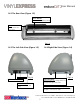
User Manual 4.2 Loading Roll Media 4.2.1 The EnduraCUT 2 can be used as a desktop plotter or with an optional floor stand (part number PLTA-VE-ENDURACUT-2S-STD). The plotter comes with brackets for use to support roll media (Fig 4.4). An optional roller tray (Part number SE-ES-ENDURATRAY) is also available and is a better solution for controlling rolls of media in a desktop configuration (Fig 4.5).
User Manual 4.2.2 After loading the media on the brackets, roller tray, or stand, pull the front edge forward under the pinch rollers. 1. Pull it toward the front edge of the platen and use the ruler to check alignment. The side edges of the media should be perpendicular to the front of the plotter. 2. After loading the roll media, flatten the media on the platen and hold the front edge of the roll media firmly to ensure that the roll is straight. 3.
User Manual 4.4 Cutting Force and Offset Adjustment Before sending your designs from computer to EnduraCUT 2 for cutting, please make “Cut Test” to adjust cutting force and offset value. The “Cut Test” should be repeated several times until the optimum settings are achieved. Please follow procedure below to optimum the cutting force and offset settings. Step1. After sizing the media, press [CUT TEST] button to select the “Square Cut”, and press [ENTER KEY] to confirm.
User Manual Step4. If the pattern appears to be BB or CC layout (see Figure 4-7), press [OFFSET KEY] to adjust the offset value until AA pattern is shown.
User Manual Chapter 5: Basic Maintenance This chapter explains the basic maintenance (i.e. cleaning the cutting plotter) required for the cutting plotter. Except for the below mentioned, all other maintenance must be performed by a qualified service technician. 5.1: Cleaning the Cutting Plotter In order to keep the cutting plotter under good condition and best performance, you need to clean the machine properly and regularly. Cleaning Precautions • Unplug the cutting plotter before cleaning.
User Manual 5.3: Cleaning the Pinch Rollers If the pinch rollers need a thorough cleaning, use a lint-free cloth or cotton swab to wipe away the accumulated dust from the rubber portion of the pinch rollers. To prevent the pinch rollers from rotating while cleaning, use your finger to hold the pinch rollers in place. To remove embedded contaminants or persistent dust, use a lint-free cloth or cotton swab moistened with rubbing alcohol. Note: The daily maintenance of your cutting plotter is very important.
User Manual Chapter 6: Troubleshooting This chapter is to help you correct some common problems you may come across. Prior to getting into the details of this chapter, please be sure that your application environment is compatible with the cutting plotter Note: Before having your cutting plotter serviced, please make sure that the malfunction is in your cutting plotter, not the result of an interface problem or a malfunction in your computer or a software problem.
User Manual 6.2 Operational Problems Some problems are caused by mechanical failure or failure of a specific operation during plotting. In such cases, an error message will be displayed on the LCM stating the problem and suggesting a solution. If the problem still exists after you have performed the recommended solutions, have your cutting plotter serviced. Error, Check Media Or Drum or X Motor Error, Check Media Or Y Motor Check Carriage Sensor or VC Motor Graph Was Clipped.
User Manual 6.3 Cutting Plotter/Computer Communication Problems The messages shown below present problems in relation to cutting plotter/computer communication. Communication Error Setup: MISC. key Note: The computer also needs to set up compatible communication parameters to the cutting plotter set up. HP-GL/2 Cmd. Error If your cutting plotter does not recognize the HP-GL/2 or HP-GL commands, please make sure the HP-GL/2 or HP-GL commands applied to your cutting plotter are used properly.
User Manual 6.4 Software Problems Check the following first: 2614 Texoma Drive Denison, TX 75020 • 980 Contract St.
User Manual 6.5 Cutting Quality Problems Note: The daily maintenance of your cutting plotter is very important. Be sure to clean up the grid drum and pinch rollers regularly for better cutting accuracy and output quality. 2614 Texoma Drive Denison, TX 75020 • 980 Contract St.
User Manual 7.1 EnduraCUT 2 Specifications Operational Method Max. Cutting Width Max. Cutting Length Max. Tracking Max. Media Loading Width Min. Media Loading Width Acceptable Material Thickness Number of Pinch Rollers Motor Drive Cutting Force Max.
User Manual 7.2 Plotter Blade Primer 2614 Texoma Drive Denison, TX 75020 • 980 Contract St.