
Instruction Manual

page
IS-TM11
6/9/2022 5 www.ledalite.com
!
ATTENTION: Install in accordance with local and national building and electric codes.
Center mark
for drilling
operation
Small Joiner
Aligners
Joiner
Aligners
Supplied
by others
Quick Wire
Connectors
(Supplied)
Module 2
Module 1
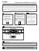
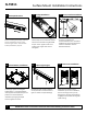
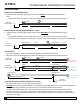
With module 2 on the ground, tap small joiner aligners
inside top chase. Ensure small joiner aligners are inserted
more than halfway inside fixture housing. Insert large joiner
aligners inside lower chase as shown.
10
Fixture Joining
11
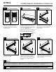
Surface Power Feed Connection
Suspend Module 2. Refer to step 7. With module 2
supported complete wiring connection using provided quick
wire connectors. Note: Do not fully raise modules at the
moment.
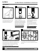
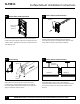
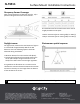
For surface junction box installation, power feed to fixture
module is done through the endcap. Use masking tape on all
outside surfaces. Align with center mark as shown and drill a
7/8” diameter hole.
9a
Surface Power Feed Preparation
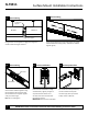
9b
Surface Power Feed Connection
Prepare power feed by installing the conduit and the
connectors (by others) to the drilled endcap. Refer to steps
16 for power connections and endcap installation.
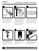
Surface Mount Installation Instructions