
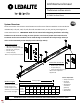
Instruction Manual

page
IS-TM11
6/9/2022 3 www.ledalite.com
!
ATTENTION: Install in accordance with local and national building and electric codes.
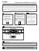
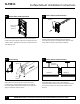
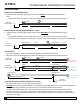
Lens Removal
1a
Lens Removal: To remove snap-in lens
for maintenance purposes, insert a flat,
smooth edged object between lens and
housing (avoid screwdrivers). Twist to
release pressure and remove lens.
Lens Removal
1b
Symmetric Fixture
Remove lens from fixture and set aside
until fixture installation is
complete. Use cotton gloves to handle
lenses and keep in a clean environment.
Remove the 2 screws securing the lower
light engine and temporarily support
light engine in position below fixture.
DO NOT ALLOW LIGHT ENGINE TO
HANG FROM ELECTRICAL WIRES.
Save screws for re-installation later.
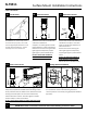
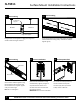
Direction
of light
1c
Asymmetric Fixture
Remove lens and set aside until fixture
installation is complete. Use cotton
gloves to handle lenses and keep in a
clean environment.
Remove the 2 screws securing the
lower light engine and temporarily
support light engine in position below
fixture.
DO NOT ALLOW LIGHT ENGINE TO
HANG FROM ELECTRICAL WIRES.
Save screws for re-installation later.
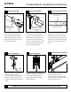
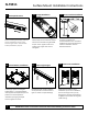
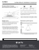
Supplied
by others
Determine location of ceiling brackets. Pull aircraft cable
thru the bracket. Center and install ceiling brackets to
structure (studs or cross-braces) using appropriate hardware
(by others).
2
Ceiling Bracket Installation
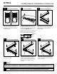
1d
Fixture with Louvers
Remove one louver from end of fixture by pulling gently and
temporarily suspend from available holes. Remaining louvers
can be pushed to center for better access. Remove the screws
securing the surface plate. For louver-lens combinations,
remove both louver and lens. Use cotton gloves to handle
lenses and keep in a clean environment.
DO NOT ALLOW LIGHT ENGINE TO HANG FROM ELECTRICAL
WIRES.
Suspension
hole
Surface
plate
Surface Mount Installation Instructions