Natural Draft Diesel Heater Operating and Installation Instruction Manual *KEEP THIS MANUAL FOR FUTURE REFERENCE* Sig100, 120, 170, 180 ** Please read from beginning to end before installing and operating. Heater’s Serial #: __________________ Quality Controlled by- Doug & Don Form#7.
WARNINGS - Do not operate this heater unattended. - Turn off the heater when refueling. - Do not burn gasoline. - When operating the heater there MUST be an open fresh air vent. - Do not light a warm burner or it can result in an explosion. - Do not use a pressurized fuel tank. - Do not plug the overflow fitting. - Install a CO alarm. - Follow ALL installation and operation procedures. 1. About a Natural Draft Diesel Heater A Sig Marine diesel heater has many advantages to other heating appliances.
water coils are available in a 1 turn coil to heat approx. 5-10 gallons of water. Hot water coils are also available in 2 turn coils to heat approx. 15-20 gallons of water. 2. Important Notes Here are some important notes to remember when installing a Sig Marine diesel heater: • Mounting & location, 12v power hook-up, minimum 4ft and a maximum 10ft of chimney, the location of hole for the chimney & the fuel supply.
It is important to create and maintain a positive pressure inside the boat. High winds can draw air out from the boat and thus create a negative pressure. This condition can result in down drafts. Ensure that when you do have windows open that they do not create a suction effect in the cabin due to the window’s position and the wind direction. In a similar way, it is possible for the air intake on your engine to suck the air out of a cabin if it is not properly vented.
the volume of air entering the boat, and the boat will gradually become depressurized. With lower pressure in the boat than outside, there will be a tendency for air to be drawn back into the boat from all available openings including down the chimney. 2. Air movement in the boat. Second, air movement in the boat must not interfere with the chimney. As air flows out through the one window, air is drawn from another to replace it.
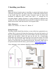
5. Installing your Heater Location Plan your heaters location prior to installing to ensure the location chosen will fit the specifications and safety clearances. Combustible material closer to the heater then the specified safety clearances must be lined with insulation or millboard and a metal liner with a .5” standoff for air movement behind. Another alternative is using insulation or millboard and ceramic tile.
Mounting The Sig heaters have the appropriate brackets to secure the heater to the bulkhead. The drip tray will then fit under the bottom of the heater. **REMEMEBER: remove all protective plastic on ALL parts of the heater. Chimney Pipe The location and configuration of the chimney stack is very important to the operation of the heater. A long, straight chimney stack will ensure a strong draft for correct operation. The diameter of the chimney must be what is specified.
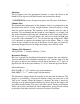
Install the barometric tee pipe with the front flap facing fore and aft. In order for the barometric to work efficiently it must be installed between 12” and 24” from the top of the heater. If using a flue guard, turn the barometric tee to the back as it does not have to be seen to work To adjust the flap on the barometric, back off the jam nut and turn the counterweight so the flap is standing closed.
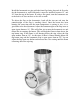
Deck Fitting To install the thru deck fitting, a hole must be cut in your deck. Depending on the diameter of the chimney stack will depend on the size hole that needs to be cut. There should be a 1” clearance all around the chimney pipe. For example, a 3” diameter exhaust pipe would require a 5” hole drilled in the deck. Once a hole is cut, you can line the raw hole with epoxy, caulking or a metal liner to finish it off. Just ensure there is a 1” air gap between the side of the hole and the chimney pipe.
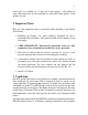
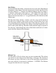
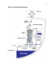
Heater Installation Diagram
6. Fuel System Installation For efficient and safe operation of the heater, follow all recommendations for properly installing the fuel system. DANGER: Never use gasoline in a heater. Use only #2 diesel, #1 stove oil or kerosene. The valves are factory calibrated to #2 diesel; if #1stove oil or kerosene is preferred, the valves can be re-calibrated to suit those viscosities.
you will need to burn off the fuel in the line before re-opening the shut-off valve. Do not use a check valve. Remember to re-open the shut-off valve on the overflow line. Fuel Filter & Manual Shut-off’s The fuel must be filtered before the fuel pump and before the oil metering valve to prevent dirt and debris from plugging up the check valves in the pump and the needle and seat in the valve.
7. Walbro Fuel Pump Installation When installing a Walbro fuel pump you must ensure it is mounted approximately at the level of the valve on the heater. These pumps can “pull” fuel but have trouble “pushing” fuel so it must be gravity fed from the pump to the heater. The lift and the climate will then indicate if you need the standard pump (part#15078) or the heavy duty pump (part#15078-1).
Once the valve is full of fuel and the pressure has been reached the fuel pump will still continue to tick, but less frequent. Once the pressure drops in the valve the pump will then begin to tick more frequent depending on the demand of fuel from the valve. To lessen the noise of the pump pulsing, a rubber backing can be installed. The pump should be included in a control circuit with a 2 amp fuse so it can be turned off when the heater is not in use.
opposite end of the spring. Replace the lid with the gasket on by lowering your finger on to the red O ring sleeve without the plunger falling out (the plunger is about 2” long so you have room to lower your finger out of the way). The red O ring sleeve will fit inside the pump tube and the black O ring will fit over the outside of the pump tube and will require twisting and pushing the lid straight back in. This is a little tight but that is what makes the seal.
8. Draft Assist Fan Installation The 12v draft assist is not needed for operation but highly recommended as it will help to vaporize the fuel and give more control in burning the heater as clean as possible. The fan is a 12v DC fan that the draw is .17amp. The fan is 12v and if 24v or 32v is needed, resistors are available.
9. Operation The first time the oil-metering valve is turned on it will take 5-10 minutes for the fuel lines to fill and oil to appear in the bottom of the burner. Lighting Procedure 1. Turn on the fuel pump or open the gravity feed valve to allow fuel to flow into the oil metering valve on the heater. 2. Open the door or open the lid and twist the superheater so the bottom makes a good contact with the bottom of the burner. 3.
11. Approximate Valve & Fan Settings Heater Temperature Fan Knob Position Cold Start Off Warm Low Off Warm Low (cold or windy) 4 to 5 o’clock Medium 5 to 6 o’clock Medium (cold or windy) 6 to 7 o’clock High 7 o’clock * Operating the fan can deliver too much air and cause the burner to run too lean (too much air in the fuel to air mixture). If you find that the flames start to burn below the top burner ring, turn the fan down slightly or increase the fuel slightly.
12. Operation Tips When operating on the lower temperature settings the burner needs less air. To reduce the air, adjust the barometric damper open wider, turn off the fan, and add more fuel even if you do not want the heat. It is better to make too much heat and dissipate it than to run the burner too lean with flames inside the burner pot as this will result in hard carbon build up and soot.
13. Flooding the Burner A vaporizing oil burner of this type can be flooded if care is not taken to prevent excess oil entering the burner when lighting. By following the lighting instructions flooding will be avoided. A flooded burner that is still burning should be turned off and the heater monitored until the oil has burned off. Use the combustion assist fan to add air to fully combust the excess fuel. Reasons that will flood your burner.
14. The Oil Metering Valve & Fuel Flow Safety Fuse A high temperature fuse is incorporated into the oil metering valve. The adjusting screw on the top of the knob of the oil metering valve is fitted with a fusible sleeve. This fuse will melt if the valve knob reaches a temperature of 165 degrees F. This will shut-off the flow of oil into the burner. Under normal conditions, the valve is at room temperature. If the high fire sleeve melts it indicates too much heat is by the valve compartment.
Fuel Flow Measurements If your heater is burning rich (making soot or smoking) or burning lean (flames not burning above the top burner ring), adjust the valve fuel flow as follows regardless of what type of fuel: 1) Unscrew the compression nut from the bottom of the valve with 2 wrenches and bend away the copper fuel line. Allow the oil to drip into a cup or container. 2) Lift and turn the valve knob to the #1 setting. Measure the quantity of oil dripping slowly from the fuel outlet.
Oil Metering Valve Repair Kit Part# 905005 *For valves made from 2007-Present All Valves made prior to 2007 are discontinued and no parts are available. 1. 2. 3. 4. 5.
Place the new copper/brass washer in, then screw in the new seat into the bottom casting until tight but not so tight as to damage the aluminum threads of the casting (35 inch pounds). • Place the new needle in the groove of the float and insert the float pin through the bracket and float, then snug up the float screw. • Loosen the float screw so the bracket will move up and down and adjust the bracket so when pushing on the needle the top of the float will be parallel with the top of the casting.
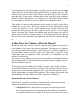
Oil Metering Valve Diagram
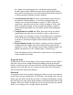
15. Burner Assembly Your diesel heater has been equipped with a Airflow burner. There are two components in the burner that must be correctly placed for the heater to operate properly. The burner ring must be placed at the top of the pot so the outside edge of the ring fits into the groove in the top of the pot. Ensure that the ring fits in evenly and snugly all the way around the pot and that all of the oval shaped slots are clearly visible. The second component is the superheater.
16. Maintenance Fuel Maintenance Checklist (CHECK ONCE A YEAR) 1) Disconnect the fuel inlet line from the valve and place into a bucket. Turn on your pump or open your gravity feed valve to ensure there is a constant flow of fuel. This will indicate your fuel filter and fuel pump are operating correctly. 2) Remove the fuel inlet fitting from the valve and clean the screen behind. 3) Replace fuel inlet line to the fuel inlet fitting.
4) Using a paperclip, poke out the four rows of twelve air intake holes on the sides of the burner to ensure they are clear of any soot. 5) Remove any loose carbon from the base of the burner. 6) Remove the reamer tool and replace burner ring and the superheater. Cleaning the Fuel Line Any blockage in the fuel line from the oil-metering valve to the burner can be cleaned by removing the clean-out plug situated directly under the burner.
*Flames are orange and dirty creating soot on the window & deck- The flames are burning too rich, this to say too much fuel and / or not enough air. Add air first by turning the fan on. Just add enough air to turn the flames vibrant yellow and not lazy orange with black tips, however adding too much air will burn off the fuel and the flames will end up below the top burner ring.
18. Warranty Policy We at Sig Marine and Dickinson Marine wish to maintain a reasonable and easy system for returns, warranty, returns and exchanges. To accomplish this, we would like to inform you of some helpful guidelines and procedures to use and follow when sending back product to the Sig Marine. All correspondence regarding returns, warranties and exchanges will go through the factory of Sig Marine in Surrey, BC, Canada and the product MUST be returned to this location.
service insured and retain a tracking number. Customers are responsible for the shipping costs for all returns and exchanges. Sig Marine Returns Unit #101-17728 66 Avenue Surrey, BC V3S 7X1, Canada 4. Products that are demonstrably older than the warranty period or those that have obviously been misused will not be returned, exchanged, or repaired. Non-defective Returns & Exchanges Sig Marine reserves the right to apply a 20% restocking fee for returned product sent back.
maintenance, which is necessary to keep your product performing its intended function and operating at a reasonable level of performance. DAMAGE LIMITATION WARNING : IN NO EVENT SHALL Sig Marine BE LIABLE FOR ANY INCIDENTAL OR CONSEQUENTIAL DAMAGES, INCLUDING (BUT NOT LIMITED TO) LOSS OF USE OF THE PRODUCT, LOSS OF TIME, INCONVENIENCE, EXPENSES FOR TRAVEL, LODGING TRANSPORTATION CHARGES, LOSS BY DAMAGE TO PERSONAL PROPERTY OR LOSS OF INCOME, PROFITS OR REVENUE.
19. Register your Warranty….. Please register your warranty with Sig Marine Marine. Fill out and send back the warranty registration below. Make sure to include the serial # for our records. No warranty will be extended for improper installations. Use of any unapproved materials, equipment, or installation procedures will result in a voided warranty. Do not use any substitutes of the heaters valve, burner or fan other then the ones supplied by Sig Marine.
Sig Marine #101-17728 66 Avenue, Surrey, B.C., V3S 7X1 Canada Tel: 604-574-8641 Fax: 604-574-8659 E-mail: info@sigmarine.com Website: www.sigmarine.com All rights reserved. No part of this manual may be reproduced without permission in writing from Sig Marine. Sig Marine also reserves the right to modify or change without notice, any materials, applications, equipment, accessories, and/or prices. All measurements and weights are approximate.